March 24, 2023

Double acting pneumatic cylinder operation using 5/2 direction control valve and PLC

 Problem Statement: -

A heavy door is to be opened or closed by a double-acting cylinder. This door will open or close with two push buttons, one push button is located inside and another push button is located outside. Draw a Ladder Diagram for the Giving Condition.

a) The push button should only work when the door is either fully open or fully closed.


Solution: -

Number of inputs = 4

PB1: Inside push button

PB2: Outside push button

L1:  Limit switch located at closing position.

L2:  Limit switch located at open position.


Number of outputs = 2

Y1: Left Solenoid of 5/2 control valve

Y2: Right Solenoid of 5/2 control valve

Pneumatic Circuit Diagram:


Answer - (a): -

 Number of inputs = 4

Possibilities = 24 =16


Description: -

Initially, as the door is fully closed the L1 limit switch is pressed (L1=1 & L2=0), the door will only open when any one of the push buttons is pressed (PB1 =1 & PB2=0 OR PB1=0 & PB2=1)

It is not possible that both the Limit switches L1 & L2 are pressed at the same time   (L1=1 & L2=1).

Both the switches are unpressed (L1=0 & L2=0), which means the door is neither fully opened nor fully closed

As the door is fully closed the L1 limit switch is pressed (L1=0 & L2=1), the door will only open when any one of the push buttons is pressed (PB1 =1 & PB2=0 OR PB1=0 & PB2=1).
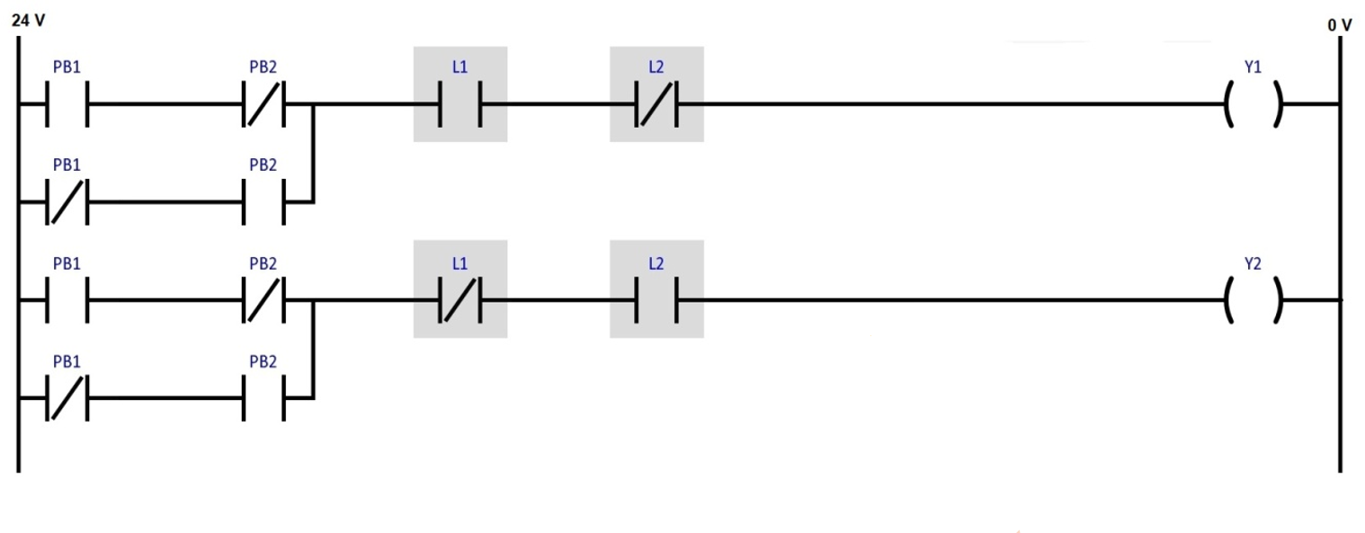
Hence, Y1= (L1) (L2)’ (PB1)’ (PB2) + (L1) (L2)’ (PB1) (PB2)’

               = (L1) (L2)’ [(PB1)’ (PB2) + (PB1) (PB2)’]


             Y2= (L1)’ (L2) (PB1)’ (PB2) + (L1)’ (L2) (PB1) (PB2)’

               = (L1)’ (L2) [(PB1)’ (PB2) + (PB1) (PB2)’]


Note: - Above application may be different from actual application. This example is only for explanation purpose only. We can use this concept in other examples also. All parameters and graphical representations considered in this example are for explanation purpose only, parameters or representation may be different in actual applications. Also, all interlocks are not considered in the application.


                                                                                            Written by Subham Prajapati

January 19, 2023

Operate the dump hopper using double acting pneumatic cylinder.

Problem Description: -

Material is to be emptied from the dump hopper. By pressing PB1 ,the dump hopper will be tilted, and bulk material is emptied out and by pressing the PB2 hopper is returned to its original position. 


Problem Diagram: -


Pneumatic Circuit: -


Solution

As Shown in diagram we can see one double acting pneumatic cylinder is used to tilt the hopper. With the cylinder open/close operation we can operate the hopper. We used two Push buttons to operate the hopper. So once operator press PB 1 , hopper will tilt at some angel and loose material will come out from the hopper and if operator will press PB 2, hopper will return to its home position.

Pneumatic circuit explanation: -

As shown in pneumatic circuit diagram, we need double acting pneumatic cylinder to operate hopper. Here we used two 3/2 valves and one double acting pneumatic cylinder for the application. If operator press PB 1 then Air flow will move from P to A so cylinder rod will come out and it will tilt the hopper. If PB2 is pressed, air flow will move from P to B so hopper will return to its original position.


Note: -Above application may be different from actual application. This example is only for explanation purpose only. We can implement this logic in other way also. All parameters and graphical representations considered in this example are for explanation purpose only, parameters or representation may be different in actual applications. Also, all interlocks are not considered in the application.


December 26, 2022

Single acting pneumatic cylinder operation using 3/2 direction control valve.

Problem Description: -

The operation of Single acting pneumatic cylinder by using two pushbuttons PB1 and PB2. PB1 is for start the operation and PB2 is for stop the operation.

Diagram: -


Here we took Single acting cylinder and 3/2 single solenoid spring return valve now we have to use electric circuit to operate solenoid.


Program: -

Here is PLC program for making START/STOP pneumatic cylinder operation using PLC.


List of Inputs/Outputs

List of Inputs

X0: -PB1

X1: -PB2

List of Outputs

Y0: -Cylinder Relay output

Ladder Diagram for single acting pneumatic cylinder operation using 3/2 direction control valve.


Program Description: -

-In the ladder diagram, we use two push button one for start (PB1) and other one to stop (PB2). And we also use relay for operate solenoid as shown in figure.

-We give direct 24 voltage to PB1 (NO) and then PB1 normally open contact to PB2 (NC) and then PB2 normally closed contact to the relay.

-Now we take one normally open contact of relay and give to the PB2 common to give continuous supply to the relay it is called latching and take second normally open contact of relay to the solenoid and give 0v to solenoid to complete circuit.

-Now when we press PB1 power supply to the relay and relay start. And by starting relay solenoid is also get power and operate valve. Now if we release PB1 but power to the solenoid will not stop because of latching.

-Now when we press PB2 contact will open stop the relay that’s why solenoid is also stop and cylinder will back at their normal position because of spring return valve.

                                                                                    By Mansuri Afnan