Run time advanced configuration in TIA portal
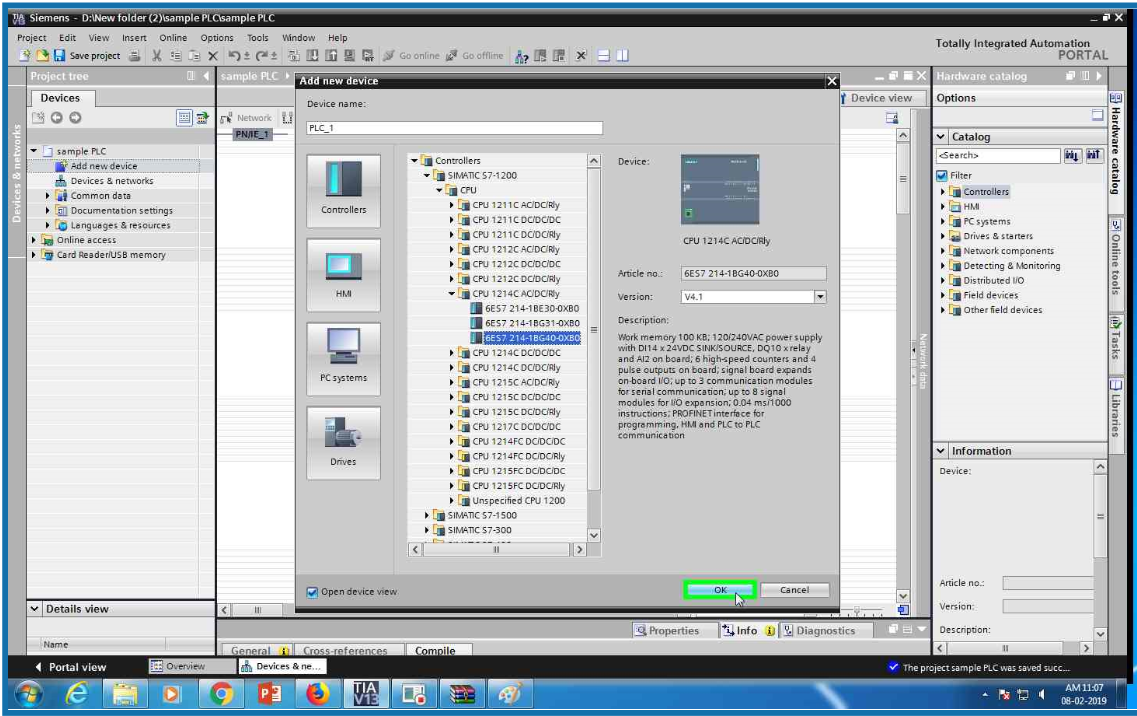
Open TIA portal and click on add new device

Select controller family from the list

Select CPU form the S7-1200 family

From the list select CPU 1214 AC/DC/RLY PLC

Select serial no 6ES7 214-1BG40-0XB0 from the list (this is for example only you ca select CPU which you have).

Click OK and done! PLC configuration.
Again add new device and open PC system family from the list

Select PC general from the list

Select PC station

Click OK

Add IE general from the hardware catalog.

Add it


Now add Wincc RT advanced from the catalog.

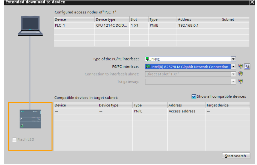
Select network view and check both IP address


Set the connection between two devices.Now RT advanced configuration completed.