While 4-20 mA signals offer superior noise immunity compared to voltage-based signals, industrial environments present numerous challenges that can degrade signal quality. Electromagnetic interference from motors, drives, and power lines; ground loops; and cable impedance issues can all affect measurement accuracy. This article explores signal conditioning techniques, noise sources, grounding strategies, and practical methods to ensure reliable 4-20 mA signal transmission in harsh industrial environments.
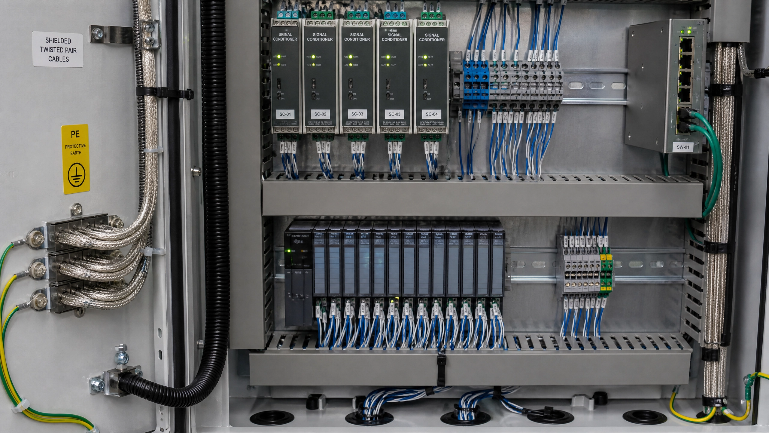
Figure 1: Industrial Control Cabinet with Shielded Cables and Signal Conditioning Equipment
Sources of Noise in Industrial Environments
Industrial facilities contain numerous sources of electromagnetic interference. Variable frequency drives (VFDs) controlling motor speeds generate high-frequency switching noise. Welding equipment creates intense electromagnetic fields. High-voltage power lines and transformers generate 50/60 Hz and harmonic interference. Radio transmitters and cellular systems introduce RF interference. Understanding these noise sources is the first step in mitigating their effects.
Conducted noise enters the signal circuit through power supply lines or ground connections. Common-mode noise appears equally on both signal conductors, while differential-mode noise appears between them. The 4-20 mA current loop is particularly immune to common-mode noise because the signal is defined by current flow through the loop, not voltage referenced to ground.
Radiated noise couples into signal cables through electromagnetic induction. Cables located near high-current conductors or high-voltage equipment experience stronger coupling. The twisted-pair geometry of industrial signal cables provides some immunity by canceling induced voltages, but additional shielding is often necessary in severe environments.
Cable Selection and Routing
Proper cable selection is fundamental to signal quality. Industrial-grade twisted-pair shielded cable is standard for 4-20 mA signals. The twisted-pair geometry ensures that any electromagnetic field induces equal voltages in both conductors, which cancel each other in the differential signal. The shield provides additional protection by intercepting radiated noise.
Cable impedance affects signal quality, particularly for long runs. Low-impedance cable (less than 100 ohms per kilometer) maintains signal integrity better than high-impedance cable. For runs exceeding 500 meters, low-impedance cable becomes increasingly important.
Cable routing significantly impacts noise coupling. Signal cables should be routed away from high-current power cables, motor leads, and VFD output cables. When crossing power cables is unavoidable, the crossing should be at right angles to minimize coupling. Keeping signal cables at least 30 centimeters from power cables is a practical guideline.
Separating signal cables from power cables in different conduits or cable trays provides better isolation than mixing them. In severe environments, running signal cables through separate shielded conduit can be justified. Some facilities use fiber optic cables for critical measurements to provide complete electrical isolation.
Shielding and Grounding
The shield in shielded cable must be properly grounded to be effective. The shield should be connected to the shield ground terminal at the PLC analog input module. At the transmitter end, the shield should typically be grounded to the transmitter chassis.
A critical principle: the shield should be grounded at only one point to prevent ground loops. If the shield is grounded at both ends, current can flow through the shield, creating a ground loop that introduces noise. The single-point grounding principle is particularly important in systems with multiple transmitters and long cable runs.
In some cases, the transmitter location may be far from the PLC, and the transmitter may be grounded to local earth ground. In these situations, the shield should be grounded at the transmitter end only, with the shield floating (ungrounded) at the PLC end. This prevents ground loop current from flowing through the shield.
Filtering and Signal Conditioning
Analog input modules typically include built-in filtering to reduce noise. A first-order low-pass filter with a 100-millisecond time constant is common. This filter removes high-frequency noise while allowing the signal to respond to actual process changes.
The filter time constant must be chosen carefully. A faster filter (shorter time constant) provides better response to process changes but less noise filtering. A slower filter provides better noise filtering but slower response. For most industrial applications, a 100-200 millisecond time constant provides a good balance.
Some applications benefit from additional external filtering. An RC filter (resistor-capacitor network) can be added between the transmitter and the PLC input to provide additional noise filtering. The filter should be designed to have minimal effect on the signal while effectively attenuating high-frequency noise.
Ferrite Clamps and Shielding
Ferrite clamps placed around signal cables provide additional noise immunity. Ferrite material absorbs high-frequency electromagnetic energy, preventing it from coupling into the signal conductors. Ferrite clamps are particularly effective for RF interference from radio transmitters and cellular systems.
Ferrite clamps should be placed as close as possible to the noise source. For a VFD output cable, placing ferrite clamps on the cable near the VFD is more effective than placing them near the motor. For signal cables, ferrite clamps should be placed at both the transmitter and PLC ends.
In severe electromagnetic environments, ferrite shielding boxes can be constructed around sensitive equipment. The transmitter or PLC input module can be placed inside a ferrite-lined enclosure, providing comprehensive shielding from external electromagnetic fields.
Isolation and Optocoupling
In some cases, complete electrical isolation between the transmitter and PLC is necessary. Isolation transformers can be used in power supply circuits to break ground loops. For signal transmission, optocoupling (using light-emitting diodes and photodiodes) provides complete electrical isolation while transmitting the signal.
Isolated 4-20 mA repeaters are available that accept a 4-20 mA input and output a new 4-20 mA signal that is electrically isolated from the input. These devices are useful for breaking ground loops in multi-transmitter systems where ground loop current would otherwise flow through the signal circuit.
Grounding Practices
Proper grounding is essential for noise immunity. The PLC enclosure should have a solid ground connection to the facility earth ground. This ground should be a low-impedance path, typically using a large copper conductor or bus bar.
Signal ground should be connected to the same ground point as power ground, but through a separate conductor to avoid coupling noise from power currents into the signal ground. In large facilities, a star grounding pattern (all grounds connected at a single point) provides better noise immunity than daisy-chain grounding.
Ground loops occur when multiple paths exist between ground points at different potentials. In a multi-transmitter system, if each transmitter is grounded to local earth ground and the PLC is grounded to a different earth ground location, ground loop current flows through the signal circuit. Careful grounding design prevents these loops.
Practical Noise Troubleshooting
When noise problems occur, systematic troubleshooting identifies the source. First, verify that the signal cable is properly shielded and grounded. Second, check that the cable is routed away from power cables. Third, verify that the PLC input module filter settings are appropriate.
If noise persists, try adding ferrite clamps to the signal cable. If noise is still present, try routing the signal cable through separate conduit away from power cables. If the problem continues, consider using an isolated 4-20 mA repeater to break ground loops.
Measurement Verification
After implementing noise reduction measures, verify that signal quality has improved. Use an oscilloscope to observe the signal voltage across the input resistor. The signal should be relatively smooth with minimal high-frequency noise. If the signal shows significant noise, additional filtering or shielding is needed.
Compare PLC readings before and after implementing noise reduction measures. Readings should be more stable and consistent. If readings still fluctuate, additional measures are necessary.
Conclusion
Maintaining signal quality in 4-20 mA systems requires attention to cable selection, routing, shielding, grounding, and filtering. While 4-20 mA signals offer inherent noise immunity compared to voltage signals, industrial environments present challenges that can degrade signal quality. Understanding noise sources, implementing proper grounding practices, using appropriate filtering, and applying shielding techniques ensures reliable signal transmission. Automation professionals who master these signal conditioning techniques can design robust measurement systems that maintain accuracy even in harsh electromagnetic environments.
Key Takeaways
•Industrial environments contain numerous sources of electromagnetic interference
•Twisted-pair shielded cable provides basic noise immunity
•Shield grounding at a single point prevents ground loops
•Filtering removes high-frequency noise while preserving signal response
•Ferrite clamps provide additional RF interference immunity
•Proper grounding practices prevent ground loop noise
•Systematic troubleshooting identifies and resolves noise problems