-Signals selection, Decisions section and Actions Section
-The sequence of the logic should be left to right
-Signals selection, Decisions section and Actions Section
-The sequence of the logic should be left to right
Application: - NORM_X and SCALE_X instructions. Explain the instruction using an example. Write the PLC program using a ladder diagram language.

Explanation
Generally, NORM_X and SCALE_X guidelines are utilized for scaling the
worth or we can utilize this guidance in simple value scaling.
By utilizing NORM_X guidance we can standardize the genuine incentive in
more slender scale inside the value range.
For instance here the info range is 0 to 27648 and this value should be
standardized indirect scaled value range from 0.0 to 1.0.
After this standardization of the worth, we can utilize this output as an information estimation of the SCALE_X guidance. This guidance maps the
incentive in the required range (here 0 to 100).
These directions for the most part utilized in Siemens S7-1200 PLC.
PLC
program:-
Write the ladder program for the above application using
ladder diagram language. Here for ladder logic, we can use any supported PLC
system like S7-1200, S7-300, S7-1500, or any other PLC which can support this
instruction. For PLC logic we need digital inputs and outputs.
Define
the memory register for the program as per the following address,
List of M Memory
MW10:-For analog value (0
to 27648).
MW12:-Out of NORM_X
MW14:-Output value


PLC
program Explanation:-
In network 1, we used NORM_X
instruction for input value conversion. So input value will be converted from
0.0 to 1.0 scale range.
In network 2, we used
SCALE_X instruction to convert NORM_X value into output. So the value will be
converted into range 0 to 100 from 0.0 to 1.0
Application:-Make a leak test system. Write PLC program for leak test system using ladder diagram language.
Diagram:-
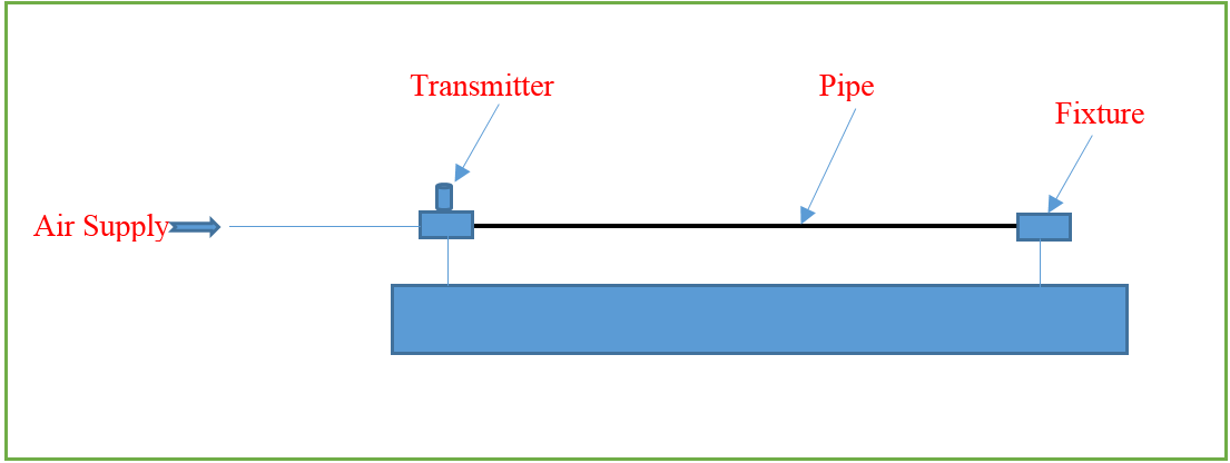
Explanation:-
As per the above
application, there is one pipe in the system. We need to check its leakage by
applying pressure up to 4- 5 bar. For leakage testing, the first pipe will be put
into the fixture and one side pipe will be blocked completely. From the other side, the pressure will be applied.
The transmitter will read
the pressure. Once the pressure achieved into the pipe, the system will close the
inlet pressure valve and hold pressure into the pipe. If there is no pressure
drop for 1 minute, the pipe is ok and if the pressure drop measured during 1 minute, the pipe is leaked.
PLC
program:-
Write the ladder program for the above application using
ladder diagram language. Here for ladder logic, we can use any supported PLC
system like S7-1200, S7-300, S7-1500 or any other PLC which can support this
instruction. For PLC logic we need digital inputs and outputs.
Digital
inputs:-
Start Button=I0.0
Digital Output:-
Inlet Valve=Q0.0
Ok lamp=Q0.1
M
Memory:-
MD24= Set Pressure
MD20=Actual Pressure
|
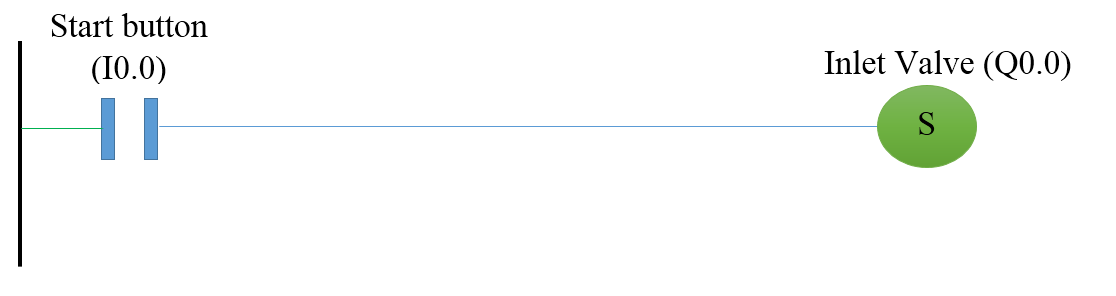
Network
1:-Inlet valve for air supply |
Network 2:-Inlet valve reset when pressure achieved

Network
3:-Indication timer for ok pipe

PLC
program Explanation:-
In network 1, the inlet valve (Q0.0) will on when the start button (I0.0) is
pressed. Here we used set coil so the output will be set after the start button
pressed.
In network 2, the inlet valve will be off when Actual pressure (MD20) is
greater or equal to set pressure (MD24).
In network 3, if the pressure will not drop from the pipe for 60 seconds, ok
indication lamp will be on.