S7-1200 PLC configuration,example creation,monitoring and downloaiding in the PLC.
First, we arechoosing TIA Portal V13 from our Start Menu anddouble click and open the program.

Here is our portalview. Now we need to choose Create new project icon. You can change yourproject name alsoyour path and you can add yourcomments. And clickthe create button.

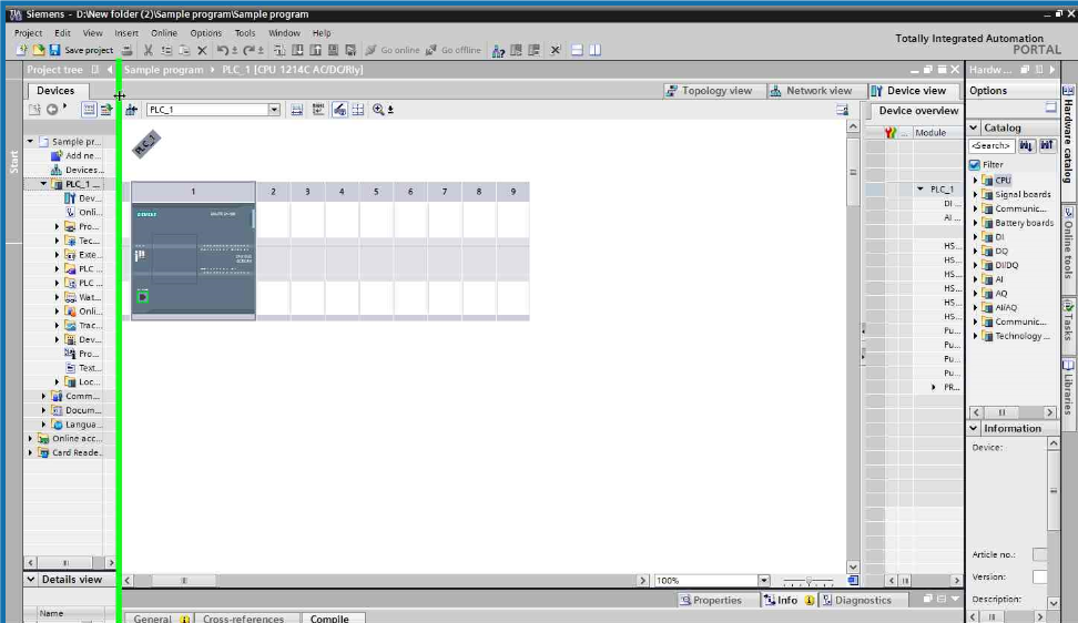
We completed Start section. Now we need to configure our device. First clickconfigure a device.

Choose add new device. And click SIMATICS7-1200 CPU its model and type respectively. Your CPU type can change from one to another. So you need to control on your PLC Training Set. Its CPU panel willgive needed information to you. When you are confident to select true choice. Click add button. And go on.

The CPU added. You can see at the following figure.Now choose Program blocks and clickdouble Main [OB1].

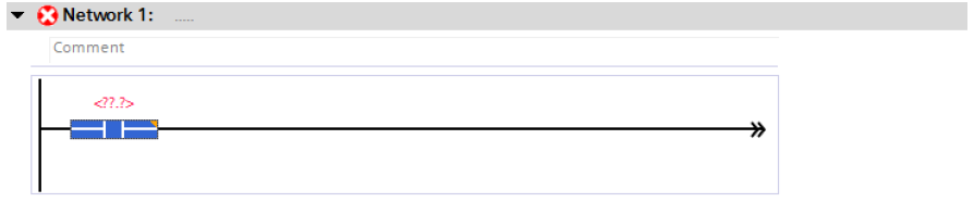
Here is the LADDER diagram window. Now we are ready to add our operations such as bit logic, timer,counter,comparator etc.We will use Basic Instructions part

Click right button on mouse. And choose Define tag.

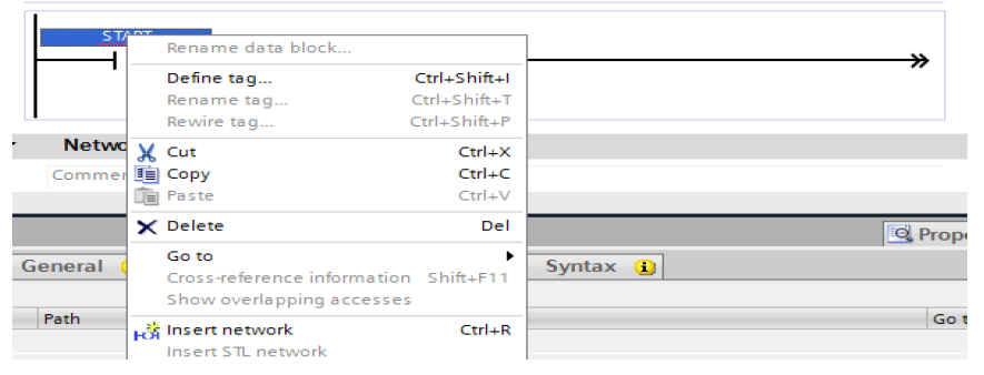
Specify your information and click the Define button. Start button’s name is I0.0
Do the same thinglike START button withSTOP button. Stop button’sname will be I0.1 This is your choice.You have no constraints on it.

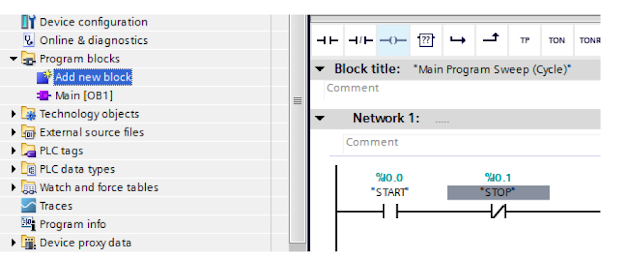
Now double click Add new block. Because we need Timer for our problem.
/////////////////////////////////////////////////////////////////////////////////////////////////////////////
Choose Data Block. FromType, so you can choose whatever you need. Andwe
choosed IEC_Timer. And click OK.


/////////////////////////////////////////////////////////////////////////////////////////////////////////////
Choose Data Block. FromType, so you can choose whatever you need. Andwe
choosed IEC_Timer. And click OK.

Our Data_block_1[DB1] is added. Double clickMain [OB1] and turn back our LAD diagram.

Add TON timer relayfrom Basic Instructions isselected. And clickunknown information on and under the timer. Our time is milisecondat our programme. You need to giveattention. Also we will giveits label ‘’Data_block_1’’. Youcan see our explanations at the following figures.

/////////////////////////////////////////////////////////////////////////////////////////////////////////////////////////
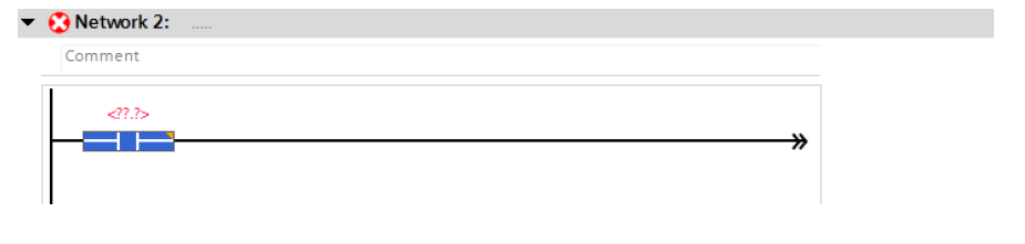
Now we need to use Network 2.
////////////////////////////////////////////////////////////////////////////////////////////////////////////////////
Add new button. Its our timer’s output contact.

We will add output coil. Its label will be MOTOR.

______________________________________________________________________________
Click right with Mouse and specify its properties and click Define button again.

This iconis downloading our program to CPU.Also you knowMain[OB1] is interface between PC and CPU. Clickdownload icon and continue.
Choose PN/IE and Intel® 82579LM Gigabit Network Connection. And click theStart Search button.
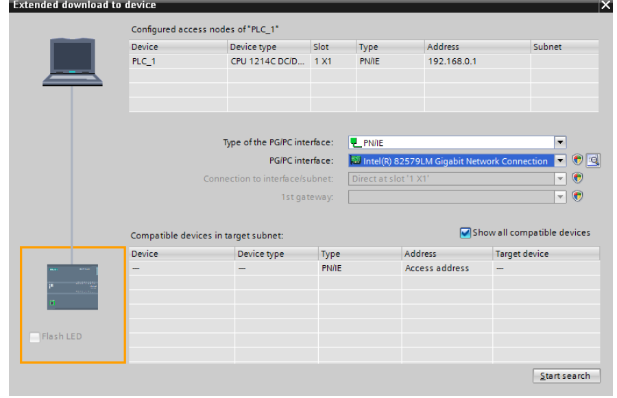
Search is completed. Choose PLC_2 device and click the Load button.

Choose Stop all and click Load again. And then click Finish button. Finally, you completed compiling process.

Now click this icon for simulation .If you open I0.0(START) input. 30 seconds later,our motor will be loaded. Let’s do that.