Count products passing on the conveyor using counter instruction (S7-1200 FBD).
This is PLC Program for counting products passing on
the conveyor using counter instruction.
Problem
Description
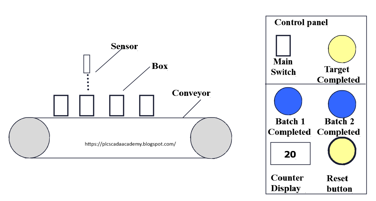
On the conveyor boxes are passing, we
need to count boxes passing on the conveyor. Write PLC program for this
application using FBD diagram language.
Problem Diagram
Problem Solution
For this
example we will use PLC programming and counter instruction.
Sensor is
used to detect the boxes passing on the conveyor and show the count value on
the display.
Here we
considered two batches so when it will be completed indication lamp will glow.
Once
production target is completed, total counter value can be reset by the reset button.
Program
Here is PLC program for counting
products passing on the conveyor using counter instruction.
List of Inputs/Outputs
Inputs
List:-
Box detector=I0.0
Reset button=
I0.1
Main SW=I0.2
Outputs List:-
Target competed
indication:- Q0.0
Batch 1
completed indication:-Q0.1
Batch 2
completed indication:-Q0.2
FBD diagram for counting products passing on the conveyor using counter instruction.


Program Description
In network 1 we've used on Main SW (I0.2) to START out the system and that we used NO contact of box detector (I0.0)
nonparallel. Here we tend to thought-about one UP counter thus once box detector (I0.0) detects box then
counter can count.
Here
additionally we've taken target completed
indication lamp (Q0.0) for target completion indication.
By
pressing RESET BUTTON (I0.1) user
will RESET the previous production record.
Counter operation boost count the boxes and RESET BUTTON (I0.1) for reset the assembly record. And preset
value (PV) is 40 products
and Counter value (CV) is MW10 for storage actual boxes on the conveyor detected by the sensor.
In network 2 we tend to took batch1 logic. Here we tend to used comparator for counting 20 boxes for batch 1 and once it'll be completed then batch 1 completed indication lamp (Q0.1) will ON.
In network 3 we tend to took batch 2 logic. Here we tend to used comparator for investigating 20 boxes for batch 1 and once it'll be completed then batch 2 competed indication lamp (Q0.2) will ON.
Note:-Application is only for learning and
educational purpose .Above application may be different from actual
application. This application can be done in other PLC also. Users are
responsible for correct operation of the PLC system and for any possible injuries
and or material damages resulting from the use of this program. It is necessary
to take care of safety during implementation, installation, maintenance and
operation.
All parameters and
graphical representations considered in this example are for explanation
purpose only, parameters or representation may be different in actual
applications. Also all interlocks are not considered in the application.


