Design and implement a PLC program in Siemens S7‑1200
that processes the analog signal from the pressure transmitter, normalizes it,
and scales it into engineering units (bar), ensuring accurate and reliable
pressure monitoring for display and control using NORMA_X and SCALE_X
 |
| PLCSCADACADEMY |
Explanation
1. Hardware Integration (S7-1200)
The S7-1200 typically features onboard analog inputs (0-10V) or uses
signal boards/modules for current signals (4-20mA).
Wiring the Pressure Transmitter
- 2-Wire
Transmitter: The transmitter is powered by the loop. The PLC
provides 24V DC.
Path: L+ →
Transmitter (+) → Transmitter (-) → PLC Input (+) → PLC Input (-) → M.
- 4-Wire
Transmitter: The transmitter has separate power and signal
wires.
Path: Signal (+)
→ PLC Input (+) | Signal (-) → PLC Input (-).
S7-1200 Addressing & Range
- Onboard
AI: Usually %IW64 and %IW66.
- Expansion
Modules: Addressing starts at %IW96 or higher.
- Digital
Range: 0 to 27648 (Normal range).
- Deadband/Wire
Break: For 4-20mA, if the raw value drops to -4864, it
indicates 0 mA (wire break).
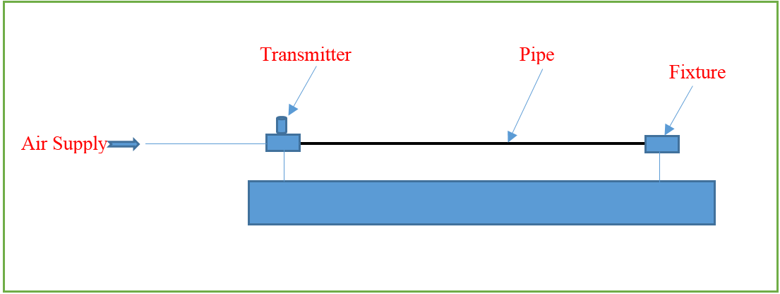
2. Technical Case Study: Pressure Measurement
Application: Monitoring a hydraulic line pressure.
- Sensor: 4-20
mA Pressure Transmitter.
- Physical
Range: 0.0 to 100.0 Bar.
- PLC: S7-1200 with an AI 4x13 bit SM 1231 module.
Signal Mapping Table
|
Pressure
(Bar) |
Signal
(mA) |
S7 Raw
Value (%IW) |
S7
Normalized (0.0 - 1.0) |
|
0.0 Bar |
4 mA |
0 |
0.00 |
|
25.0 Bar |
8 mA |
6,912 |
0.25 |
|
50.0 Bar |
12 mA |
13,824 |
0.50 |
|
75.0 Bar |
16 mA |
20,736 |
0.75 |
|
100.0Bar |
20 mA |
27,648 |
1.00 |
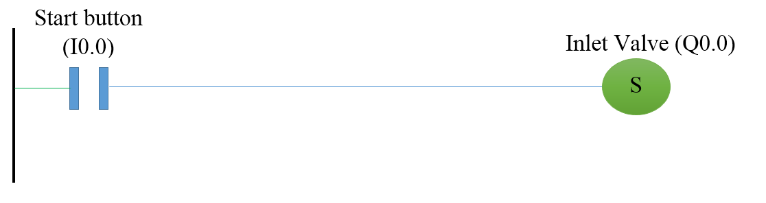
PLC program:-
Write the ladder program for the above application using
ladder diagram language. Here for ladder logic, we can use any supported PLC
system like S7-1200, S7-300, S7-1500, or any other PLC which can support this
instruction. For PLC logic we need digital inputs and outputs.
Define
the memory register for the program as per the following address,
List of M Memory
MW10:-For analog value (0
to 27648). ( Convert int to real for real value )
MW12:-Out of NORM_X
MW14:-Output value
 |
| PLCSCADAACADEMY |
 |
| PLCSCADAACADEMY |
PLC program Explanation:-
Network 1 – Input Value Conversion (NORM_X)
- Instruction
used: NORM_X
- Purpose: To
normalize the raw analog input value into a floating‑point number between 0.0
and 1.0.
- Why
needed:
- Analog
input modules return integer values (e.g., 0 to 27648 for 0–20
mA).
- These
raw values are not directly meaningful in engineering terms.
- Normalization
ensures that no matter the input range, the value is scaled into a standardized
ratio (0.0–1.0).
Process:
- The
PLC reads the raw analog input (e.g., 0–27648).
- NORM_X
divides the input by the maximum possible value.
![]()
- Result
is always between 0.0 (minimum) and 1.0 (maximum).
Example:
- Raw
input = 13,824 (half of 27,648)
- Normalized
value = 0.5
So, the sensor signal is now expressed as a percentage of full scale.
Network 2 – Output Value Conversion (SCALE_X)
- Instruction
used: SCALE_X
- Purpose: To convert
the normalized value (0.0–1.0) into a desired engineering unit range.
- Why
needed:
- Engineers
want values in real units (temperature, pressure, speed, etc.).
- SCALE_X
maps the normalized ratio into the chosen engineering range.
Process:
- Take
the normalized value from Network 1.
- Multiply
it by the engineering unit span (Max – Min).
- Add
the minimum engineering unit value.
![]()
Example:
- Normalized
value = 0.5
- Engineering
unit range = 0–100
- Calculation:
![]()
So, the PLC output is 50 units (e.g., 50.0 bar if measuring bar).
Putting It Together
- Network
1 (NORM_X): Converts raw sensor signal → normalized ratio
(0.0–1.0).
- Network
2 (SCALE_X): Converts normalized ratio → engineering units
(0–100).
This two‑step process ensures:
- Flexibility
(any input range can be normalized).
- Accuracy
(engineering values are scaled correctly).
- Simplicity
(easy to reuse across different sensors and outputs).