This is PLC Program for Machine Lubrication Control
Problem Description
The goal is to ensure that the lubrication system is activated before the machine starts. The lubrication should only occur when the machine is in the "ready to start" state, and the lubrication process should stop after a predefined period, ensuring that the machine is properly lubricated before operation.
Problem Diagram
Problem Solution
In this example, we aim to solve the problem using simple conditional logic. We have a gearbox motor that requires lubrication before it can be started.
To achieve this, we use a lubrication motor that supplies lubrication oil to the main gearbox motor. We will implement an interlock system to ensure that the operator cannot operate the main motor directly.
Here’s how the system works:
The operator must first start the lubrication motor (pump) before they can operate the main gearbox motor.
This interlock ensures that the gearbox motor is properly lubricated, which helps in maintaining its longevity.
The operator uses dedicated start and stop push buttons for each motor:
- Lubrication Motor (Pump): Start and Stop push buttons.
- Main Gearbox Motor: Separate Start and Stop push buttons.
With this setup, we ensure the gearbox motor receives the necessary lubrication before operation, thus protecting it and extending its operational life.
Program
Here is PLC Program for Machine Lubrication Control.
List of Inputs/Outputs
Inputs List: -
Cycle Start PB: -I0.0
Cycle stop PB: -I0.1
Oil Pump Start PB-I0.3
Oil Pump Stop PB-I0.2
Main Motor Start PB-I0.5
Main Motor Stop PB-I0.4
Outputs List:-
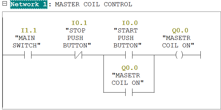
Master coil:-Q0.0
Oil Pump Motor-Q0.1
Main Motor-Q0.2
Function block diagram to provide lube for the machine.
Program Description
In the first and second networks, we use a set-reset circuit. The master coil can be started by pressing the Cycle Start PB and stopped by pressing the Cycle Stop PB.
In network 3, the oil pump can be started by pressing the Oil Pump Start PB and stopped by pressing the Oil Pump Stop PB.
In network 4, the main motor can be started by pressing the Main Motor Start PB and stopped by pressing the Main Motor Stop PB.
Note: -Application is only for learning purpose .Above application may be different from actual application. This application can be done in other PLC also. Users are responsible for correct operation of the PLC system and for any possible injuries and or material damages resulting from the use of this program. It is necessary to take care of safety during implementation, installation, maintenance and operation.
All parameters and graphical representations considered in this example are for explanation purpose only, parameters or representation might be different in actual applications. Also all interlocks are not considered in the application.