Software Used: TIA portal 15.1
CPU used : S7-1200 1214C DCDCDC CPU SIEMENS
Click "Read More" For video
Please like, Share and Subscribe our YouTube Channel : A Creative - YouTube
Subscribe Our Channel : Free Subscribe!!
Software Used: TIA portal 15.1
CPU used : S7-1200 1214C DCDCDC CPU SIEMENS
Click "Read More" For video
Please like, Share and Subscribe our YouTube Channel : A Creative - YouTube
Subscribe Our Channel : Free Subscribe!!
Software Used: TIA portal v15.1
CPU used : S7-1200 1214C DCDCDC CPU SIEMENS
Click "Read More" For video
Please like, Share and Subscribe our YouTube Channel : A Creative - YouTube
Subscribe Our Channel : Free Subscribe!!
Small part hot plate welding.
Application:-Weld two small plastic parts with the hot plate welding method.
Write the PLC program for the hot plate welding process using a ladder diagram
language.
Diagram:-

Explanation:-
Hot plate welding the method is a popular method for plastic part welding in the plastic industry.
Generally, two parts are melted at a certain temperature and joint together in
this method. We can use this method for two plastic parts welding.
-Signals selection, Decisions section and Actions Section
-The sequence of the logic should be left to right
Design and implement a PLC program in Siemens S7‑1200
that processes the analog signal from the pressure transmitter, normalizes it,
and scales it into engineering units (bar), ensuring accurate and reliable
pressure monitoring for display and control using NORMA_X and SCALE_X
 |
| PLCSCADACADEMY |
Explanation
1. Hardware Integration (S7-1200)
The S7-1200 typically features onboard analog inputs (0-10V) or uses
signal boards/modules for current signals (4-20mA).
Wiring the Pressure Transmitter
Path: L+ →
Transmitter (+) → Transmitter (-) → PLC Input (+) → PLC Input (-) → M.
Path: Signal (+)
→ PLC Input (+) | Signal (-) → PLC Input (-).
S7-1200 Addressing & Range
2. Technical Case Study: Pressure Measurement
Application: Monitoring a hydraulic line pressure.
Signal Mapping Table
|
Pressure
(Bar) |
Signal
(mA) |
S7 Raw
Value (%IW) |
S7
Normalized (0.0 - 1.0) |
|
0.0 Bar |
4 mA |
0 |
0.00 |
|
25.0 Bar |
8 mA |
6,912 |
0.25 |
|
50.0 Bar |
12 mA |
13,824 |
0.50 |
|
75.0 Bar |
16 mA |
20,736 |
0.75 |
|
100.0Bar |
20 mA |
27,648 |
1.00 |
PLC program:-
Write the ladder program for the above application using
ladder diagram language. Here for ladder logic, we can use any supported PLC
system like S7-1200, S7-300, S7-1500, or any other PLC which can support this
instruction. For PLC logic we need digital inputs and outputs.
Define
the memory register for the program as per the following address,
List of M Memory
MW10:-For analog value (0
to 27648). ( Convert int to real for real value )
MW12:-Out of NORM_X
MW14:-Output value
 |
| PLCSCADAACADEMY |
 |
| PLCSCADAACADEMY |
PLC program Explanation:-
Network 1 – Input Value Conversion (NORM_X)
Process:
![]()
Example:
So, the sensor signal is now expressed as a percentage of full scale.
Network 2 – Output Value Conversion (SCALE_X)
Process:
![]()
Example:
![]()
So, the PLC output is 50 units (e.g., 50.0 bar if measuring bar).
Putting It Together
This two‑step process ensures:
Application:-Make a leak test system. Write PLC program for leak test system using ladder diagram language.
Diagram:-
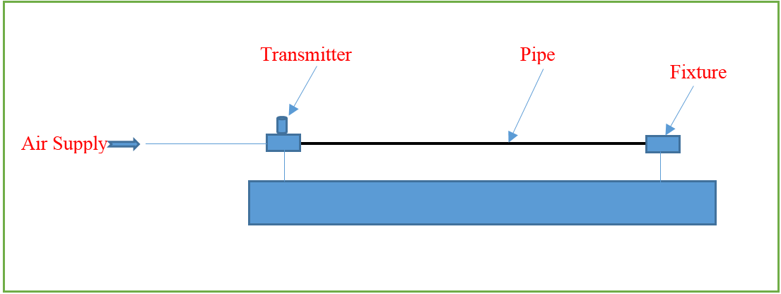
Explanation:-
As per the above
application, there is one pipe in the system. We need to check its leakage by
applying pressure up to 4- 5 bar. For leakage testing, the first pipe will be put
into the fixture and one side pipe will be blocked completely. From the other side, the pressure will be applied.
The transmitter will read
the pressure. Once the pressure achieved into the pipe, the system will close the
inlet pressure valve and hold pressure into the pipe. If there is no pressure
drop for 1 minute, the pipe is ok and if the pressure drop measured during 1 minute, the pipe is leaked.
PLC
program:-
Write the ladder program for the above application using
ladder diagram language. Here for ladder logic, we can use any supported PLC
system like S7-1200, S7-300, S7-1500 or any other PLC which can support this
instruction. For PLC logic we need digital inputs and outputs.
Digital
inputs:-
Start Button=I0.0
Digital Output:-
Inlet Valve=Q0.0
Ok lamp=Q0.1
M
Memory:-
MD24= Set Pressure
MD20=Actual Pressure
|
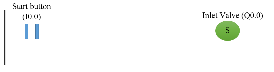
Network
1:-Inlet valve for air supply |
Network 2:-Inlet valve reset when pressure achieved

Network
3:-Indication timer for ok pipe

PLC
program Explanation:-
In network 1, the inlet valve (Q0.0) will on when the start button (I0.0) is
pressed. Here we used set coil so the output will be set after the start button
pressed.
In network 2, the inlet valve will be off when Actual pressure (MD20) is
greater or equal to set pressure (MD24).
In network 3, if the pressure will not drop from the pipe for 60 seconds, ok
indication lamp will be on.
Explain increment instruction in the PLC using an example.
Application:-Understand the concept of increment instruction in the PLC.
Write the PLC program using a ladder diagram language to understand the concept.
Diagram:-

Explanation:-
The increment instruction is used to add value.it
will add 1 in input/output value. Generally, this instruction is used to increment
the value of the application. For example, if you want to count value
periodically. Example purpose we have taken here HMI so the user can enter value
and instruction will increment the value.
So for that, we can take the input/output register for
example. Here MW 20 is the input/output register.
PLC
program:-
Write the ladder program for NEG instruction using
ladder diagram language. Here for ladder logic, we can use any supported PLC
system like S7-1200, S7-1500, or any other PLC which can support this
instruction. In our application, we have used S7-1200 PLC for reference.
M
Memory:-
Input/output value:-MW20
|
Network
1:- INC instruction operation |

PLC
program Explanation:-
In network 1,
we have taken increment instruction. So 1 value will be added into MW 20
register. Hence IN/OUT+1=IN/OUT