Successfully integrating 4-20 mA sensors and transmitters with programmable logic controllers requires understanding both the hardware connections and the software configuration. PLC analog input modules serve as the interface between the analog 4-20 mA signal world and the digital PLC environment.
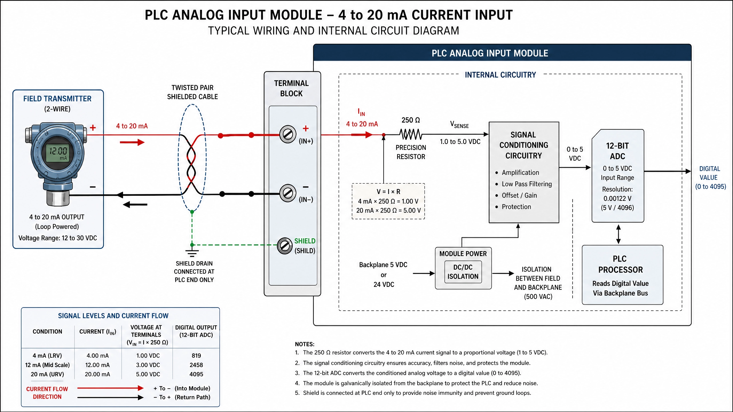
4-20 mA Signal Path from Transmitter to PLC Processing
This article explores the practical aspects of hardware integration, module selection, configuration, and troubleshooting of 4-20 mA inputs in PLC systems.
PLC Analog Input Module Architecture
A typical PLC analog input module contains several key components: terminal blocks for signal connections, signal conditioning circuitry, analog-to-digital converters (ADCs), and communication interfaces. The signal conditioning stage includes the precision resistor (usually 250 ohms) that converts the 4-20 mA current to a 1-5 volt signal. This voltage is then amplified and filtered to remove noise before being converted to digital counts by the ADC.
Most modern PLC analog input modules use 12-bit or 16-bit ADCs. A 12-bit ADC produces values from 0 to 4095 counts, while a 16-bit ADC produces values from 0 to 65535 counts. The higher resolution of 16-bit modules provides better accuracy and finer resolution, making them preferable for applications requiring high precision.
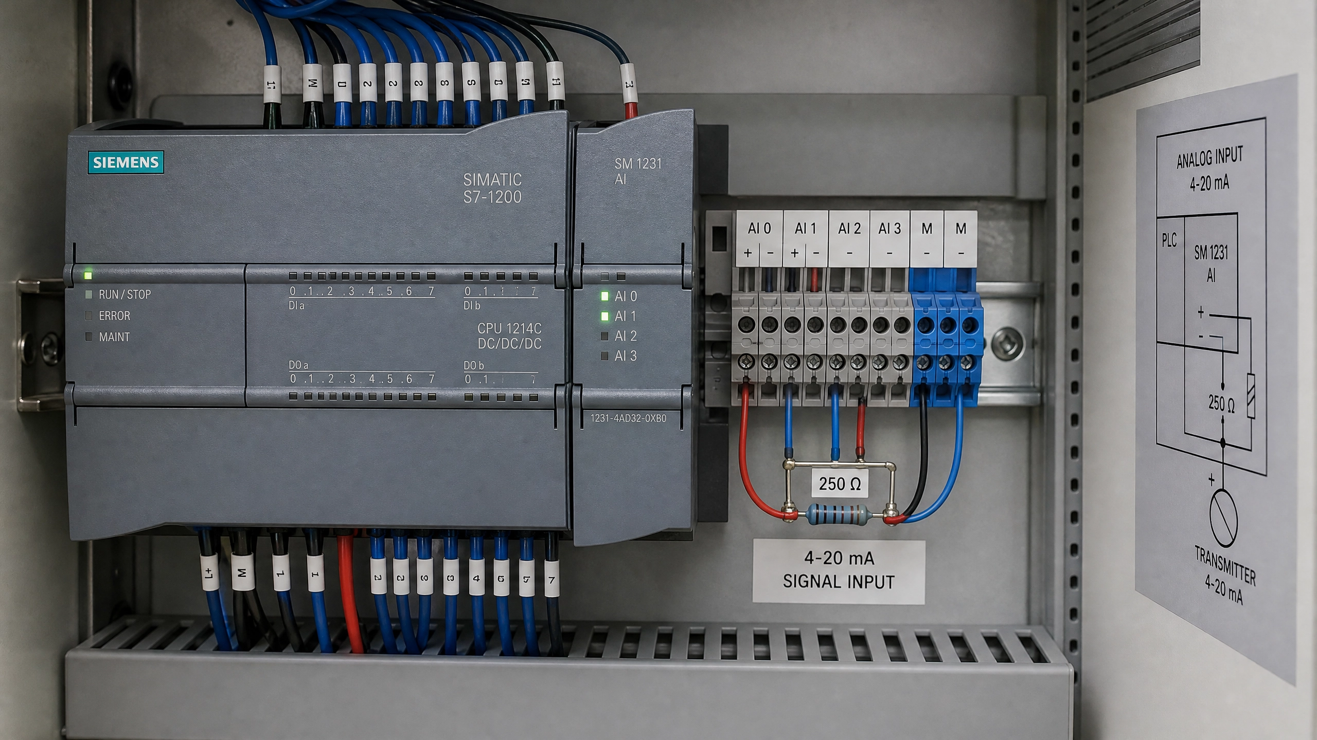
Hardware Connection Considerations
Proper physical connection of 4-20 mA signals to PLC input modules is critical for reliable operation. Each analog input channel typically has three terminals: positive signal input, negative signal return (common), and shield ground. The 4-20 mA signal flows from the transmitter through the positive terminal, through the precision resistor in the input module, and returns through the common terminal.
The shield ground connection deserves special attention. The shielded cable used for 4-20 mA signals should have its shield connected to the shield ground terminal at the PLC module. This connection provides a return path for electromagnetic interference, significantly improving noise immunity. The shield should be connected at only one end—typically at the PLC module end—to prevent ground loops that can introduce noise into the signal.
Cable selection significantly impacts signal quality. Industrial-grade twisted-pair shielded cable is standard for 4-20 mA signals. The twisted pair geometry helps cancel electromagnetic interference, while the shield provides additional protection. Cable impedance should be less than 100 ohms per kilometer. For long cable runs (over 500 meters), low-impedance cable becomes increasingly important.
Transmitter Power Supply Considerations
4-20 mA transmitters require power to operate. Two-wire transmitters draw their power from the signal loop itself, while three-wire and four-wire transmitters have separate power connections. Understanding the transmitter power requirements is essential for proper system design.
Two-wire transmitters are the most economical, using only two wires for both power and signal. The loop power supply must provide sufficient voltage to overcome the voltage drops across the transmitter, cable, and input module resistor. A typical 24 VDC power supply is standard, providing adequate voltage for most installations. The power supply must also include current limiting to protect the circuit from short circuits.
Three-wire transmitters use one wire for power supply common, one for signal positive, and one for signal negative. Four-wire transmitters have completely separate power and signal circuits, providing the best performance but requiring more wiring. The choice between these configurations depends on application requirements, budget, and available infrastructure.
PLC Module Configuration
Configuring the PLC analog input module involves several steps. First, the module must be physically installed in the PLC chassis and properly seated to ensure good electrical contact. Second, the module must be recognized by the PLC system software and assigned to the appropriate I/O address space. Third, the module parameters must be configured to match the signal characteristics.
Key configuration parameters include the input range (typically 4-20 mA or 0-10 V), the number of active channels, the sampling rate, and the filter settings. The input range configuration tells the module how to scale the raw ADC counts to engineering units. Most modules allow selection between different standard ranges or custom ranges.
The sampling rate determines how frequently the module reads the analog input. Typical sampling rates range from 10 to 1000 samples per second. Higher sampling rates provide faster response but increase computational load. For most industrial applications, 100 samples per second provides adequate response while maintaining reasonable performance.
Filter settings reduce noise in the analog signal. Most modules offer selectable filters with different time constants. A first-order low-pass filter with a 100-millisecond time constant is typical for industrial applications. Faster filters provide better response but may not adequately suppress high-frequency noise. Slower filters provide better noise suppression but may cause lag in signal response.
Software Implementation in SCL
In Siemens TIA Portal using SCL, reading 4-20 mA analog inputs involves accessing the analog input data from the module and applying the appropriate conversion calculations. The PLC automatically converts the analog signal to digital counts, but the programmer must convert these counts to engineering units.
A typical SCL implementation looks like:
Plain Text
ORGANIZATION_BLOCK "AnalogInput"
VERSION : 0.1
END_ORGANIZATION_BLOCK
Calibration and Verification
After installation and configuration, the system must be calibrated to ensure accurate measurements. Calibration involves comparing the PLC reading with a known reference value and adjusting the conversion parameters if necessary.
A typical calibration procedure involves applying known current values to the input and recording the corresponding PLC readings. At minimum, calibrate at two points: 4 mA (0% of range) and 20 mA (100% of range). For higher accuracy, calibrate at three or more points across the measurement range.
If the readings don't match the expected values, the offset and scale parameters should be adjusted. Offset adjusts the zero point of the measurement, while scale adjusts the full-scale reading. Most PLC systems provide easy methods to adjust these parameters without modifying the core program logic.
Troubleshooting Common Issues
Several common problems can occur with 4-20 mA input integration. If the PLC reads a constant value regardless of transmitter output, the signal connection is likely broken or the module is not properly configured. If the reading fluctuates wildly, inadequate filtering or poor cable shielding is usually the cause.
If the reading is consistently offset from the expected value, calibration adjustment is needed. If the reading is scaled incorrectly (for example, showing double the expected value), the scaling parameter needs adjustment. If the reading occasionally drops to zero, a loose connection or intermittent break in the signal cable is likely.
Redundancy and Diagnostics
Modern PLC systems often include redundancy features for critical measurements. Dual analog input modules reading the same transmitter provide backup if one module fails. The PLC can compare the two readings and alert the operator if they diverge beyond a threshold, indicating a potential problem.
Diagnostic features in the analog input module can detect various fault conditions: open circuit (broken wire), short circuit, out-of-range signal, and module hardware failures. These diagnostics are typically reported through status registers that the PLC program can monitor.
Conclusion
Successful integration of 4-20 mA signals with PLC analog input modules requires attention to hardware connections, proper module configuration, accurate software implementation, and thorough testing. Understanding the signal path from transmitter through input module to PLC memory, combined with knowledge of configuration options and troubleshooting techniques, enables automation professionals to build reliable measurement systems. Whether implementing temperature monitoring, pressure control, or flow measurement, mastering these integration techniques is essential for effective industrial automation.
Key Takeaways
•Analog input modules convert 4-20 mA signals to digital counts using precision resistors and ADCs
•Proper cable selection and shielding significantly impact signal quality
•Configuration parameters must match the transmitter and application requirements
•SCL programs must convert raw counts to engineering units using appropriate formulas
•Calibration at multiple points ensures accurate measurements
•Diagnostic features help identify and troubleshoot connection and hardware problems
No comments:
Post a Comment