Flow measurement is critical in countless industrial processes: monitoring fluid consumption, controlling chemical dosing, tracking product throughput, and managing utility usage. The 4-20 mA standard provides an ideal method for transmitting flow measurements from diverse flow meter technologies to central PLC systems. This article explores flow measurement principles, various flow meter types, conversion methods, and practical PLC implementations for flow monitoring and control.
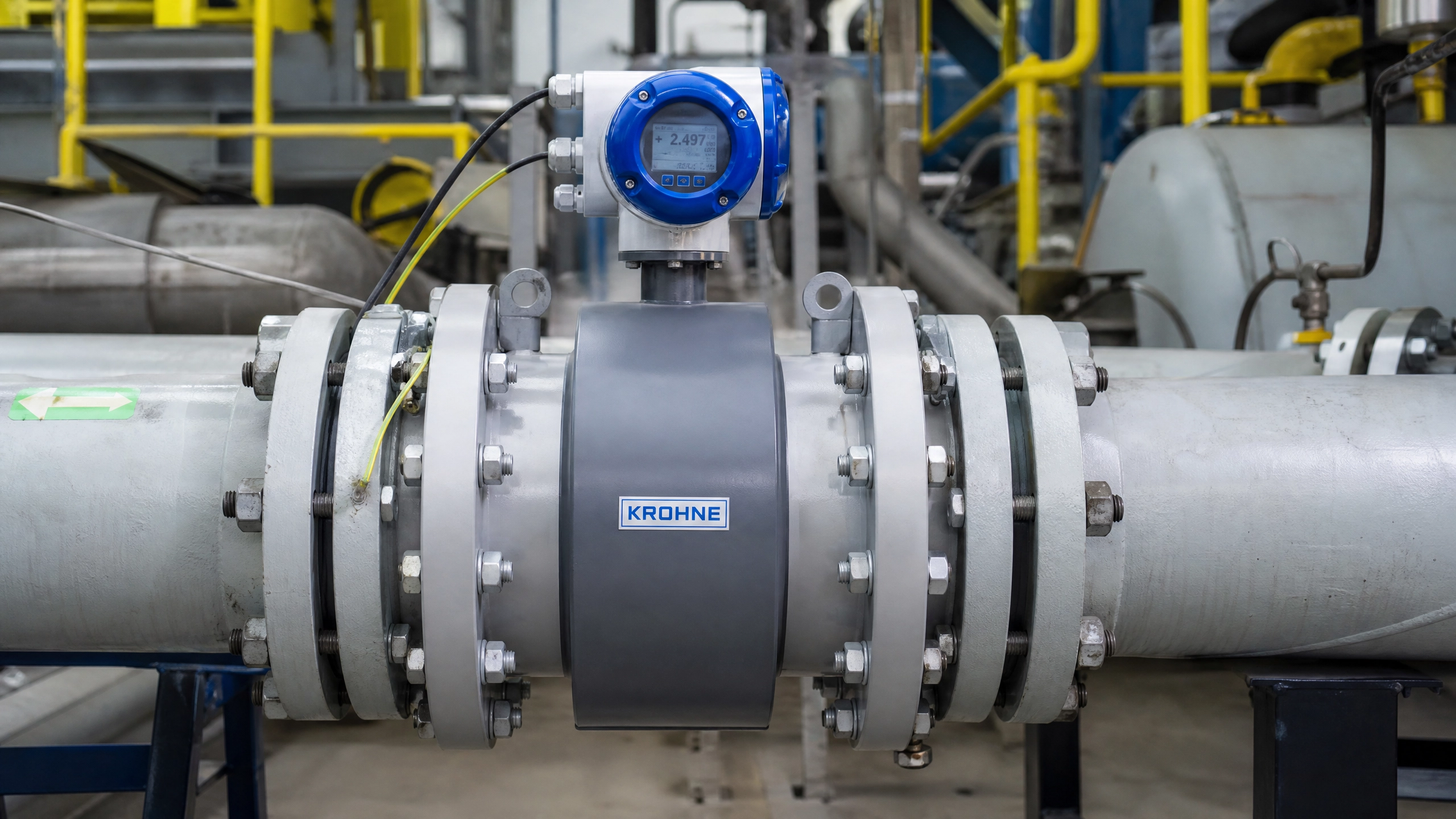
Figure 1: Industrial Electromagnetic Flow Meter with 4-20 mA Output
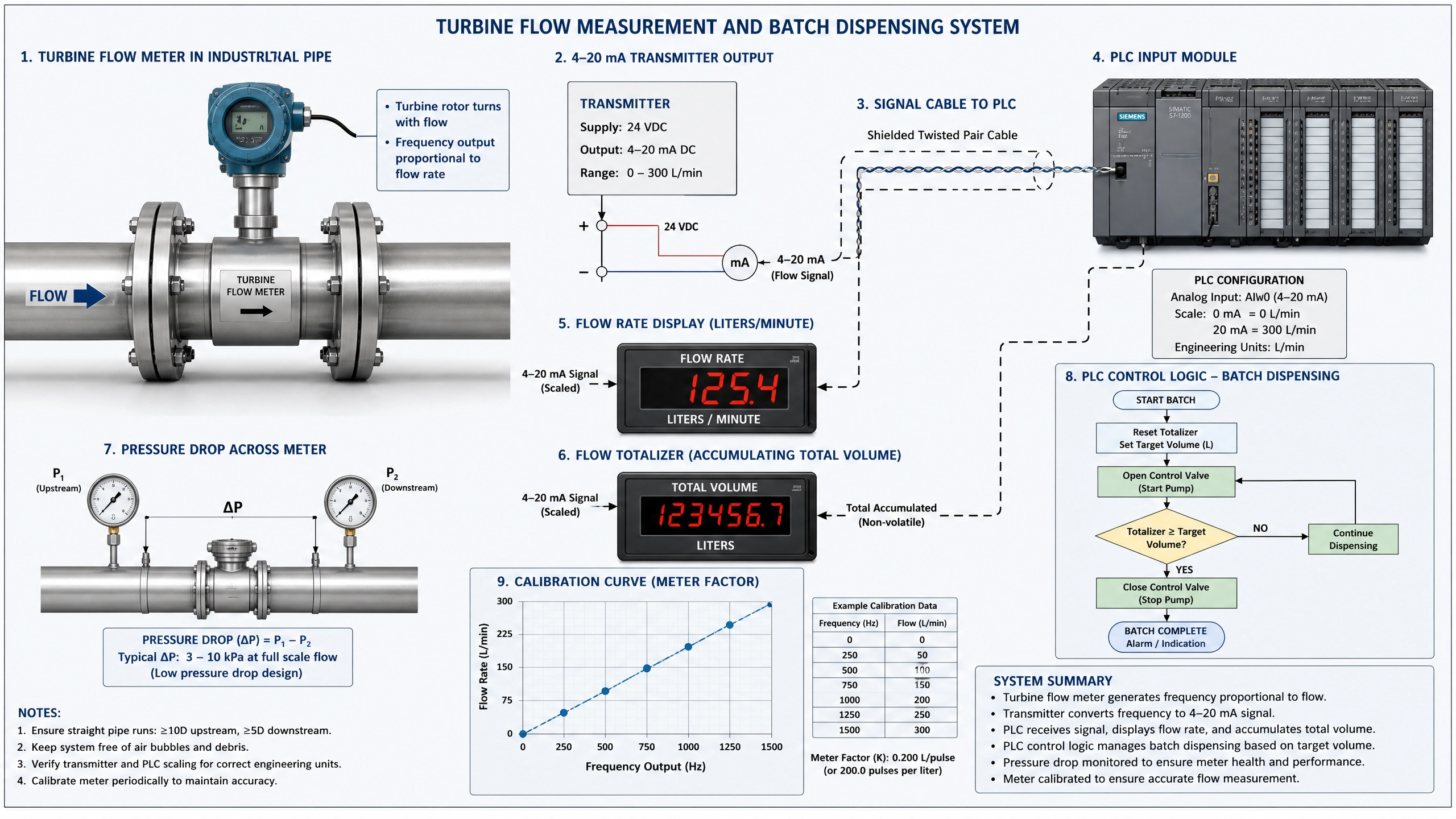
Figure 2: Flow Measurement Technologies Comparison
Flow rate represents the volume or mass of fluid passing through a point per unit time. Common units include liters per minute (L/min), gallons per minute (GPM), cubic meters per hour (m³/h), and kilograms per second (kg/s). Flow measurement is more complex than pressure or temperature because flow rate depends on fluid properties, pipe diameter, and flow conditions.
Flow meters can be classified as volumetric (measuring volume) or mass flow meters (measuring mass). Volumetric flow measurement is simpler and more common, while mass flow measurement is essential for applications where fluid density varies. Most industrial 4-20 mA flow transmitters are volumetric, outputting 4 mA at zero flow and 20 mA at maximum flow.
Turbine Flow Meters
Turbine flow meters consist of a rotor with blades that spin as fluid flows through. The rotation speed is proportional to flow rate. A magnetic pickup detects the rotor blade passages, generating pulses. An electronic transmitter converts these pulses to a 4-20 mA output.
Turbine meters offer good accuracy (typically ±0.5% to ±1.0%), wide flow ranges, and low pressure drop. They work well with clean liquids like water, diesel, and light oils. However, they're sensitive to fluid viscosity and particle contamination. Turbine meters are commonly used in water distribution systems, fuel dispensing, and chemical dosing applications.
A turbine flow meter might be configured for 0-100 L/min, outputting 4 mA at 0 L/min and 20 mA at 100 L/min. The PLC reads this signal and converts it to flow rate. The transmitter's internal electronics handle the conversion from rotor speed to current output.
Electromagnetic Flow Meters
Electromagnetic (mag) flow meters use Faraday's law of electromagnetic induction. As conductive fluid flows through a magnetic field, a voltage is induced proportional to flow velocity. Electrodes detect this voltage, which is converted to a 4-20 mA output by the transmitter.
Mag meters offer excellent accuracy (±0.5%), work with any conductive fluid, and have no moving parts. They're ideal for wastewater, slurries, and corrosive fluids where other meters would fail. The main disadvantage is higher cost compared to other technologies.
Mag meters are commonly used in water treatment plants, chemical processing, and mining operations. They're particularly valuable for measuring slurry flow, where particles would damage turbine meters. A mag meter configured for 0-50 m³/h provides accurate flow measurement regardless of fluid viscosity or particle content.
Vortex Flow Meters
Vortex meters exploit the principle that fluid flowing around an obstruction creates alternating vortices. The frequency of vortex shedding is proportional to flow velocity. A pressure sensor detects the vortex-induced pressure oscillations, and an electronic transmitter converts this to a 4-20 mA output.
Vortex meters offer good accuracy (±1%), work with gases and liquids, and have no moving parts. They're suitable for steam measurement, which is difficult with other technologies. The main limitation is that vortex meters require straight pipe sections upstream and downstream to function properly.
Vortex meters are commonly used for steam flow measurement in power plants and process facilities. A vortex meter configured for 0-100 kg/h of steam provides accurate measurement for energy management and process control.
Ultrasonic Flow Meters
Ultrasonic flow meters use sound waves to measure flow. Transit-time meters measure the time difference between upstream and downstream sound propagation. Doppler meters measure the frequency shift of sound reflected from particles in the fluid. Electronic transmitters convert these measurements to 4-20 mA outputs.
Ultrasonic meters offer non-invasive measurement (no obstruction in the flow path), work with most fluids, and have no moving parts. They're ideal for applications where pressure drop must be minimized or where the pipe cannot be modified. Accuracy is typically ±2% to ±3%, lower than other technologies but acceptable for many applications.
Ultrasonic meters are commonly used for water flow measurement in municipal systems and for energy monitoring in district heating systems. They're also used in applications where the fluid is corrosive or contains particles that would damage other meter types.
Positive Displacement Flow Meters
Positive displacement (PD) meters measure flow by repeatedly filling and emptying a known volume. As fluid flows, the meter's internal mechanism rotates, and each rotation represents a fixed volume. A pulse output is converted to 4-20 mA by a transmitter.
PD meters offer excellent accuracy (±0.5%), work with viscous fluids, and provide high resolution. They're ideal for custody transfer applications where billing accuracy is critical. The main disadvantage is higher pressure drop compared to other technologies.
PD meters are commonly used for fuel dispensing, chemical metering, and hydraulic flow measurement. A gear-type PD meter configured for 0-50 L/min provides accurate measurement for precise chemical dosing in manufacturing processes.
Flow Measurement Calculations in PLC
Converting 4-20 mA flow signals to engineering units in the PLC follows the standard conversion formula. For a flow meter configured for 0-100 L/min:
Plain Text
ORGANIZATION_BLOCK "FlowMeasurement"
VAR
raw_count : INT;
flow_rate : REAL;
max_flow : REAL := 100.0; // 100 L/min
total_volume : REAL := 0.0;
cycle_time : REAL := 0.1; // 100 ms
END_VAR;
END_ORGANIZATION_BLOCK
Practical Flow Control Application
A practical application involves controlling flow through a valve to maintain a setpoint. Consider a chemical dosing system where precise flow rate is critical:
Plain Text
ORGANIZATION_BLOCK "FlowControl"
VAR
flow_rate : REAL;
setpoint : REAL := 50.0; // 50 L/min
valve_position : INT; // 0-100%
error : REAL;
proportional_gain : REAL := 2.0;
END_VAR;
END_ORGANIZATION_BLOCK
Flow Totalizer Implementation
Many applications require tracking total volume dispensed. A flow totalizer accumulates volume over time:
Plain Text
ORGANIZATION_BLOCK "FlowTotalizer"
VAR
flow_rate : REAL; // L/min
total_volume : REAL := 0.0; // Liters
batch_size : REAL := 1000.0; // Target: 1000 liters
batch_complete : BOOL := FALSE;
cycle_time : REAL := 0.1; // 100 ms
END_VAR;
END_ORGANIZATION_BLOCK
Flow Measurement Calibration
Flow meters must be calibrated to ensure accurate measurements. Calibration involves comparing meter output with a known reference. For turbine meters, this typically involves measuring the volume dispensed over a known time period. For mag meters, calibration is often performed by the manufacturer.
Periodic recalibration is recommended, typically annually for critical applications. Calibration drift can occur due to wear, contamination, or electronic component aging.
Conclusion
Flow measurement using 4-20 mA transmitters provides reliable monitoring for diverse industrial applications. From turbine meters for clean liquids to mag meters for slurries, various technologies enable accurate flow measurement in different conditions. Understanding flow measurement principles, transmitter types, conversion methods, and PLC implementation enables automation professionals to design and maintain effective flow monitoring and control systems that optimize industrial processes and ensure product quality.
Key Takeaways
•Various flow meter technologies (turbine, mag, vortex, ultrasonic, PD) offer different advantages
•Transmitter configuration defines the 4-20 mA output relationship to flow rate
•PLC programs convert raw counts to flow rate using standard formulas
•Flow totalizers accumulate volume for batch control and metering
•Closed-loop flow control maintains setpoints through valve adjustment
•Regular calibration ensures accurate flow measurement
No comments:
Post a Comment