Converting 4-20 mA analog signals to meaningful engineering units is one of the most fundamental tasks in PLC programming and industrial automation. While the concept is straightforward, mastering the mathematical principles and understanding the various calculation methods is essential for accurate process control and reliable system operation. This article explores the mathematical foundations of 4-20 mA signal conversion and provides practical calculation methods used in real-world industrial applications.
Basic Linear Conversion Formula
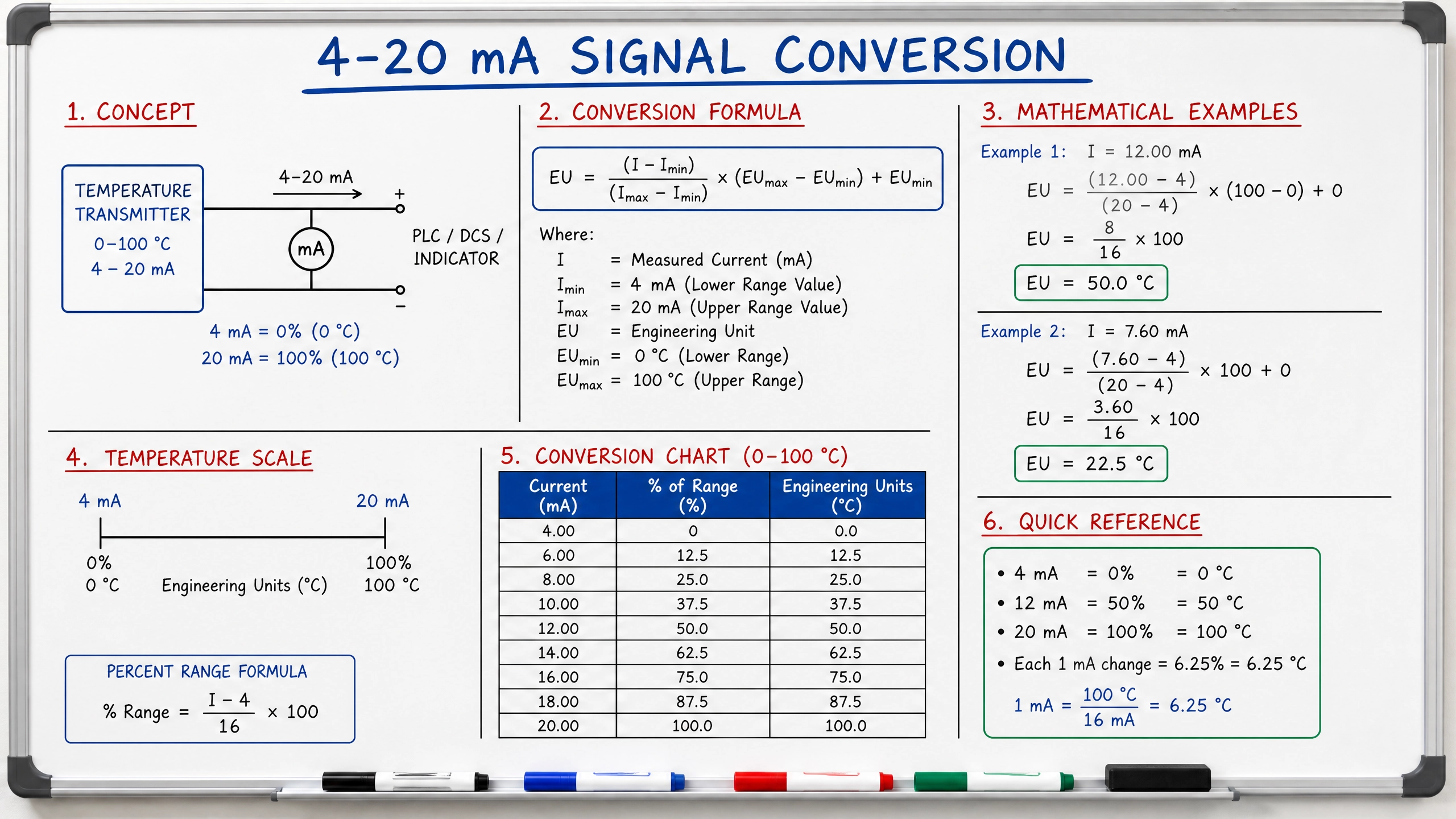
The most common 4-20 mA signal conversion uses a linear relationship between current and the measured parameter. The fundamental formula for converting current to engineering units is:
Engineering Value = (Current - 4) / 16 × (Maximum Value - Minimum Value) + Minimum Value
Where:
•Current = the measured current in milliamps (4-20 mA)
•Minimum Value = the engineering unit value at 4 mA
•Maximum Value = the engineering unit value at 20 mA
This formula works because the 4-20 mA range spans 16 mA (20 - 4 = 16), which represents the full scale of the signal. By subtracting 4 from the current value, we normalize the signal to a 0-16 mA range. Dividing by 16 gives us a percentage (0-1), which we then scale to the engineering unit range.
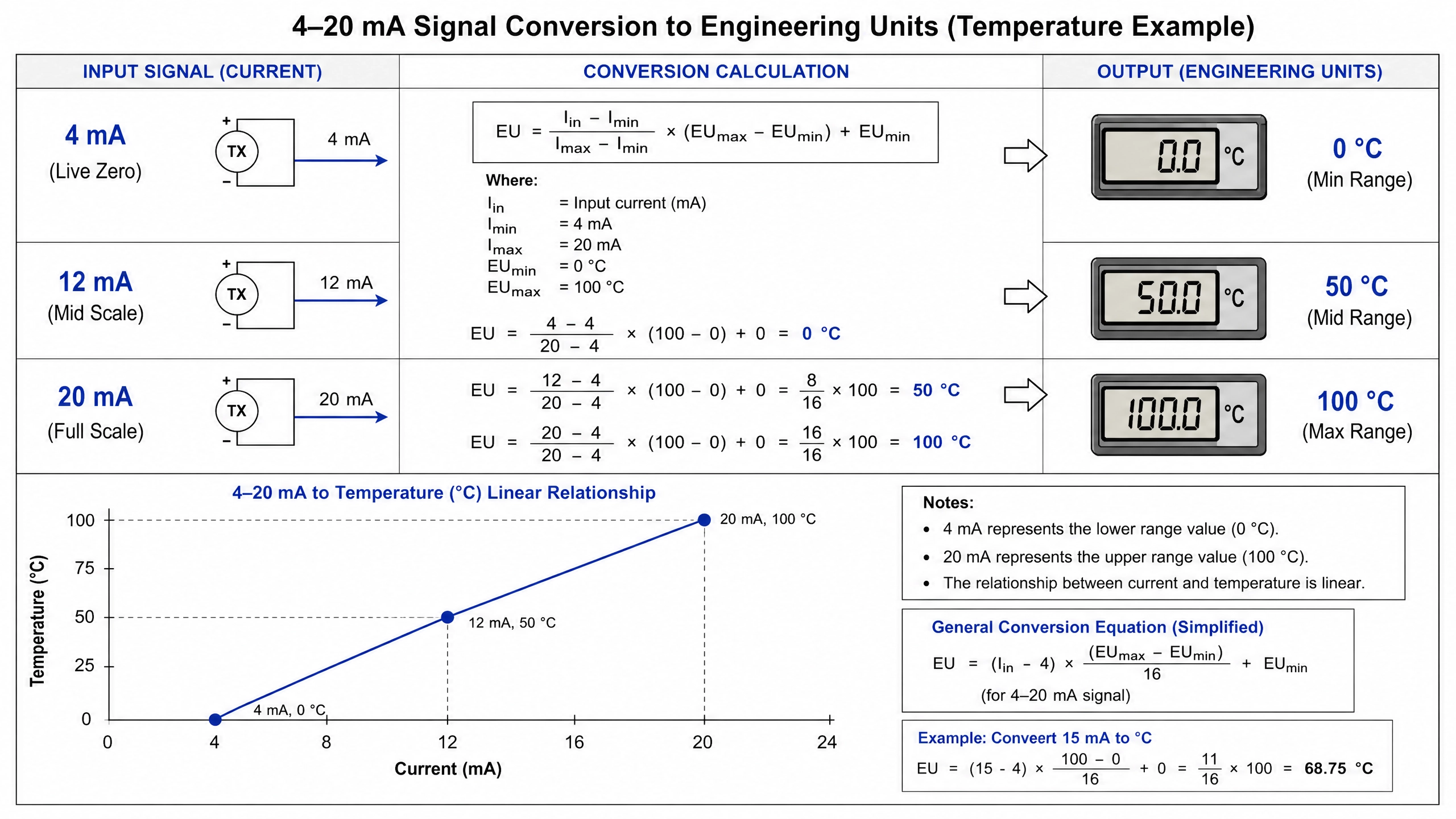
Practical Example: Temperature Measurement
Consider a temperature transmitter with a range of 0°C to 100°C. At 0°C, the transmitter outputs 4 mA, and at 100°C, it outputs 20 mA. If the PLC reads 12 mA from the transmitter, what is the actual temperature?
Using the formula:Temperature = (12 - 4) / 16 × (100 - 0) + 0Temperature = 8 / 16 × 100 + 0Temperature = 0.5 × 100 + 0Temperature = 50°C
This calculation shows that 12 mA corresponds to exactly 50% of the full scale, which equals 50°C.
Pressure Measurement with Negative Values
The 4-20 mA conversion becomes more complex when the minimum engineering value is negative. Consider a pressure transmitter measuring differential pressure from -50 PSI to +50 PSI. At -50 PSI, the output is 4 mA, and at +50 PSI, the output is 20 mA.
If the PLC reads 8 mA, the pressure is:Pressure = (8 - 4) / 16 × (50 - (-50)) + (-50)Pressure = 4 / 16 × 100 + (-50)Pressure = 0.25 × 100 - 50Pressure = 25 - 50Pressure = -25 PSI
The calculation correctly handles negative values by including them in the formula. The key is ensuring that the minimum and maximum values are correctly identified and applied.
Reverse Calculation: Converting Engineering Units to Current
Sometimes, engineers need to determine what current value corresponds to a specific engineering unit value. This reverse calculation is useful when testing transmitters or setting alarm thresholds. The reverse formula is:
Current = (Engineering Value - Minimum Value) / (Maximum Value - Minimum Value) × 16 + 4
For example, if a temperature transmitter has a range of 0°C to 100°C, and we want to know what current corresponds to 75°C:
Current = (75 - 0) / (100 - 0) × 16 + 4Current = 0.75 × 16 + 4Current = 12 + 4Current = 16 mA
This calculation shows that 75°C corresponds to 16 mA, which is 75% of the full scale.
Voltage-Based Conversion
Many PLC analog input modules convert the 4-20 mA signal to voltage before digitization. A standard 250-ohm resistor is commonly used in the input circuit, creating a 1-5 volt range (4 mA × 250 Ω = 1 V; 20 mA × 250 Ω = 5 V).
When working with voltage measurements, the conversion formula becomes:
Engineering Value = (Voltage - 1) / 4 × (Maximum Value - Minimum Value) + Minimum Value
Where the voltage ranges from 1 to 5 volts. If a PLC reads 3 volts from a temperature transmitter with a 0-100°C range:
Temperature = (3 - 1) / 4 × (100 - 0) + 0Temperature = 2 / 4 × 100 + 0Temperature = 0.5 × 100 + 0Temperature = 50°C
Digital Count Conversion
Modern PLCs convert analog signals to digital counts using analog-to-digital converters (ADCs). A 12-bit ADC produces values from 0 to 4095 counts. However, the actual usable range for 4-20 mA signals is typically 819-4095 counts (corresponding to 4-20 mA).
The conversion formula for digital counts is:
Engineering Value = (Count - 819) / 3276 × (Maximum Value - Minimum Value) + Minimum Value
Where 3276 represents the span of usable counts (4095 - 819 = 3276).
If a 12-bit ADC reads 2457 counts for a temperature transmitter with a 0-100°C range:
Temperature = (2457 - 819) / 3276 × (100 - 0) + 0Temperature = 1638 / 3276 × 100 + 0Temperature = 0.5 × 100 + 0Temperature = 50°C
Handling Non-Linear Transmitters
While most 4-20 mA transmitters are linear, some specialized transmitters use non-linear output curves. For example, certain flow meters use square root relationships to provide better resolution at lower flow rates. These require custom conversion functions rather than simple linear formulas.
Non-linear conversions typically involve lookup tables or polynomial equations. A lookup table approach stores discrete calibration points and interpolates between them. A polynomial approach uses mathematical functions to calculate the engineering value directly from the current or voltage input.
Scaling and Offset Calculations
In practice, PLC programmers often use scaling and offset parameters to simplify calculations. The general form is:
Engineering Value = (Raw Input - Offset) × Scale
For a 4-20 mA signal with 0-100°C range, the offset would be 4 (the minimum current), and the scale would be 100/16 = 6.25 (the engineering unit range divided by the current range).
This approach allows programmers to enter calibration parameters once during system setup, and the PLC automatically applies them to all measurements.
Accuracy and Resolution Considerations
The accuracy of 4-20 mA conversions depends on several factors: transmitter accuracy, ADC resolution, and calculation precision. A typical industrial transmitter maintains ±0.5% accuracy, while a 12-bit ADC provides approximately ±0.025% resolution. The overall system accuracy is typically limited by the transmitter accuracy.
Resolution refers to the smallest change in engineering units that the system can detect. With a 12-bit ADC and a 0-100°C range, the resolution is approximately 0.024°C. This means the system can distinguish between values separated by about 0.024°C.
Common Calculation Errors
Several common mistakes can compromise 4-20 mA conversions. First, using incorrect minimum and maximum values leads to completely wrong results. Second, forgetting to subtract 4 from the current value produces calculations offset by 25%. Third, using voltage instead of current (or vice versa) without proper conversion factors introduces significant errors. Fourth, failing to account for negative engineering values causes sign errors in calculations.
Conclusion
Accurate 4-20 mA signal conversion is fundamental to reliable industrial automation systems. The linear conversion formula provides a straightforward method for most applications, while specialized techniques handle non-linear transmitters and digital systems. Understanding the mathematical principles, recognizing common errors, and applying appropriate calculation methods ensures that PLC systems accurately interpret sensor signals and maintain precise process control. Whether working with temperature, pressure, flow, or level measurements, mastering these calculation techniques is essential for automation professionals.
Key Takeaways
•The basic conversion formula: (Current - 4) / 16 × (Max - Min) + Min
•Reverse calculation determines current from engineering units
•Voltage and digital count conversions use similar principles with different scaling factors
•Non-linear transmitters require custom conversion functions
•Accuracy depends on transmitter quality and ADC resolution
•Common errors include wrong min/max values and unit confusion