PLC Program: Single Tank Level Control with Alarm Acknowledgment
Problem Description:
Design a PLC-based control system to monitor and maintain the water level in a single tank. The system should:
-
Automatically control the water filling process.
-
Trigger a high-level alarm when the tank reaches its maximum threshold.
-
Include an acknowledgement button to reset the alarm after it is triggered.
Problem Diagram

Problem Solution
To solve this problem, we are using PLC programming for automatic control of the tank water level. Two level sensors are used for measurement:
-
One sensor is placed at the low level.
-
The second sensor is placed at the high level.
A feeding valve is used for filling the tank, and a discharge valve is used for emptying the tank. Both valves are controlled automatically based on sensor inputs:
-
When the water level falls below the low-level sensor, the feeding valve is activated to start filling the tank.
-
When the water level reaches the high-level sensor, the discharge valve is activated to start emptying the tank.
Program
Here
is PLC program for single tank level controlling with alarm
controlling using PLC.
List
of inputs/outputs
Digital
inputs:-
Main switch:-I1.1
Start button:-I0.0
Stop button:-I0.1
High level:-I0.2
Low level:-I0.3
Feeding valve:-Q0.1
Discharge valve:-Q0.2
Digital
outputs:-
Master coil:-Q0.0
Feeding valve:-Q0.1
Discharge valve:-Q0.2
Mixer motor:-Q0.3
Ladder
diagram for single tank level controlling with alarm controlling using PLC.
 |
| https://plcscadaacademy.blogspot.com/ |
 |
| https://plcscadaacademy.blogspot.com/ |
 |
| https://plcscadaacademy.blogspot.com/ |
 |
| https://plcscadaacademy.blogspot.com/ |
 |
| https://plcscadaacademy.blogspot.com/ |
 |
| https://plcscadaacademy.blogspot.com/ |
Program Description
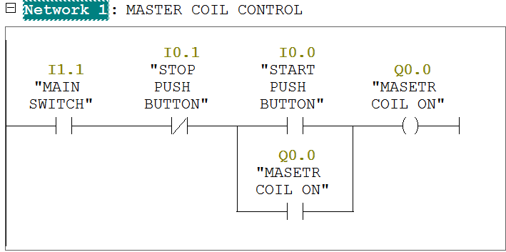
In network 1 we tend to
used latching circuit for master coil ON
(Q0.0) output.it will be
started by pressing START Push button (I0.0) and stop by pressing STOP
pushbutton (I0.1).
When cycle are going to be begin then system check level of the
tank. If tank level is low then then feeding method can begin and tank level is high then
Discharge cycle can begin.
Here we've taken NO contact for each sensors within the program for simplicity. It will be done by relay logic in field otherwise you will choose such variety of sensors.
In network 2,when tank can observe low level then low level sensor (I0.2) is going to be
activated and feeding cycle are going
to be ON. Here we've
taken NC contact of high level sensor
(I0.3) therefore once PLC can observe high
level then it'll STOP feeding
cycle.
In network 3,when tank can observe high level then high
level sensor (I0.3) is to
be activated and discharging cycle are going to be ON. Here we've
taken NC contact of low level sensor (I0.2) therefore once PLC can observe low level then it'll STOP discharge cycle.
In network 4,
mixer motor (Q0.3) will remain ON when discharge valve is ON.
In network 5 when high level (I0.3) is detected, alarm
(Q0.4) will be activated.
In network 6 when acknowledge button is pressed, alarm
will be reset.
Note:-Application is only for learning and
educational purpose .Above application may be different from actual
application. This application can be done in other PLC also. Users are
responsible for correct operation of the PLC system and for any possible
injuries and or material damages resulting from the use of this program. It is
necessary to take care of safety during implementation, installation,
maintenance and operation.
All parameters and
graphical representations considered in this example are for explanation
purpose only, parameters or representation may be different in actual
applications. Also all interlocks are not considered in the application.