Electric motors are the workhorses of industry, driving everything from small pumps to massive conveyor systems. However, the way these motors are started can significantly impact their lifespan, the mechanical integrity of the driven equipment, and the overall efficiency of an electrical system. Choosing the appropriate motor starting method is a critical engineering decision that balances factors like inrush current, starting torque, cost, and control sophistication.
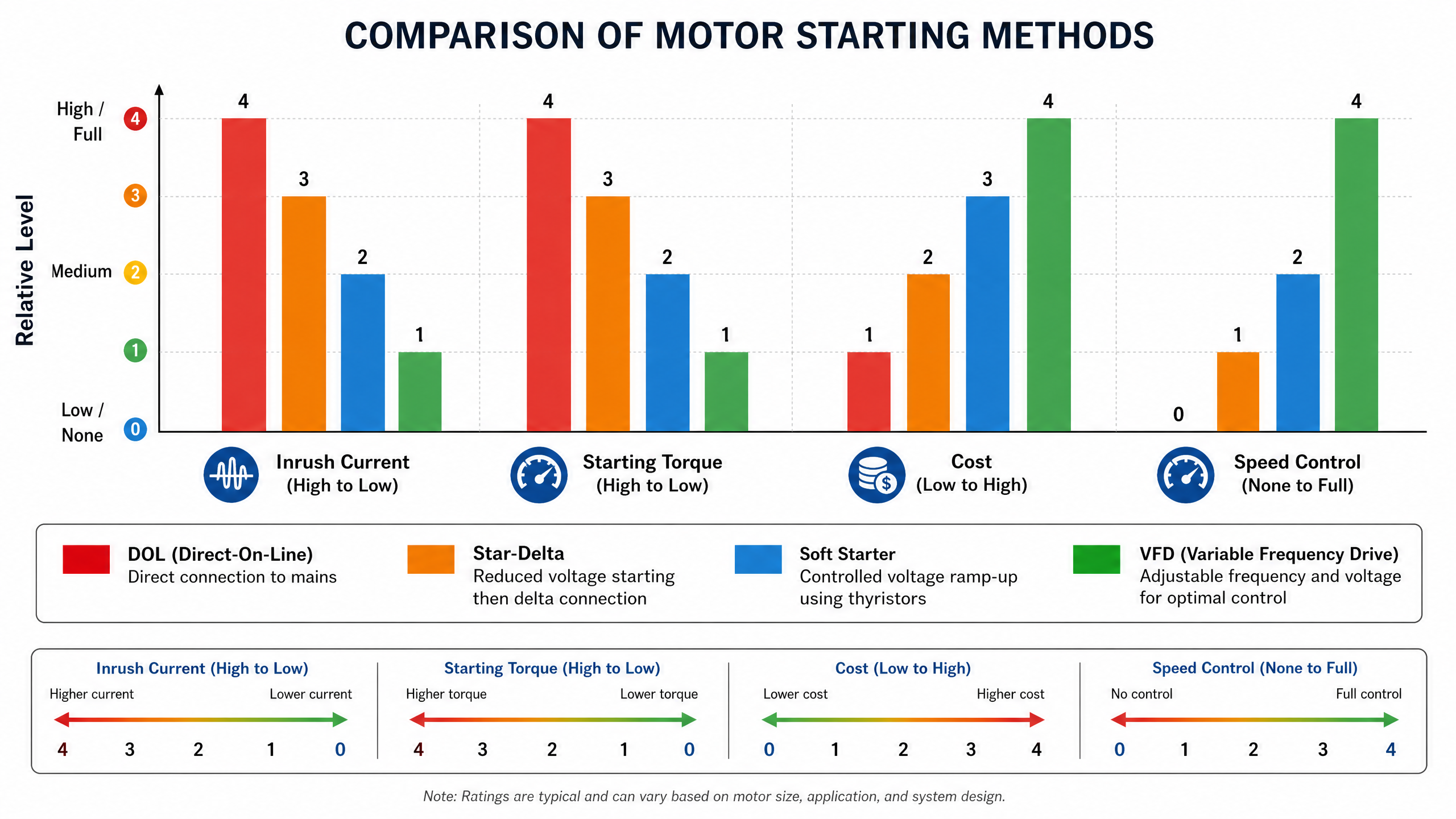
This comprehensive guide will explore the most common motor starting methods: Direct-On-Line (DOL), Star-Delta (Wye-Delta), Soft Starters, and Variable Frequency Drives (VFDs). We will delve into their operational principles, advantages, disadvantages, and ideal applications to help you make an informed choice for your specific needs.