The 4-20 milliampere (mA) current loop standard represents one of the most fundamental and widely adopted signal transmission methods in industrial automation and process control.

Established over seven decades ago, this analog signal standard continues to dominate modern industrial environments despite the proliferation of digital communication protocols. Understanding the 4-20 mA standard is essential for anyone working with programmable logic controllers (PLCs), sensors, transmitters, and industrial instrumentation.
The 4-20 mA standard defines a current-based analog signal transmission method where 4 mA represents the minimum (0%) signal level and 20 mA represents the maximum (100%) signal level. This seemingly simple concept has become the backbone of countless industrial applications, from temperature measurement and pressure monitoring to flow rate detection and level sensing. The widespread adoption of this standard across industries speaks to its reliability, simplicity, and effectiveness in transmitting analog signals over long distances with minimal signal degradation.
Historical Context and Evolution
The 4-20 mA standard emerged in the 1950s as a solution to the limitations of voltage-based analog signals. Early industrial systems relied on 0-10 volt signals, which proved susceptible to noise, voltage drops over long cable runs, and signal degradation. Engineers recognized that current-based signals offered superior noise immunity and could maintain signal integrity over extended distances without requiring expensive shielding or signal conditioning.
The choice of 4-20 mA specifically was deliberate and strategic. The 4 mA minimum value, rather than 0 mA, serves a critical purpose: it allows for detection of broken wires or disconnected sensors. If a wire breaks, the current drops to zero, which is easily distinguishable from the 4 mA minimum signal. This built-in diagnostics capability provided a significant safety advantage over voltage-based systems. The 20 mA maximum was chosen as a safe upper limit that wouldn't cause excessive power dissipation in the circuit while remaining practical for most industrial applications.
Technical Principles
The 4-20 mA current loop operates on the principle of constant current transmission. Unlike voltage signals that can vary due to impedance changes and cable resistance, current signals remain relatively constant throughout the transmission path. This fundamental difference makes current loops inherently more robust and reliable for industrial applications.
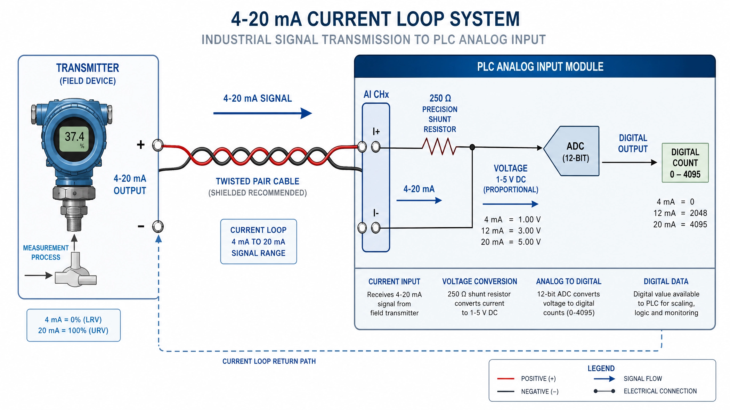
A typical 4-20 mA loop consists of several key components: a signal source (transmitter), a power supply, connecting wires, and a signal receiver (PLC input module). The transmitter generates a current proportional to the measured parameter, and this current flows through the circuit loop. The receiver measures the voltage drop across a precision resistor (typically 250 ohms) to determine the current value. The voltage drop is then converted to a digital representation for processing by the PLC.
The mathematical relationship is straightforward: if a 250-ohm resistor is used in the receiver circuit, a 4 mA current produces a 1-volt drop (4 mA × 250 Ω = 1 V), and a 20 mA current produces a 5-volt drop (20 mA × 250 Ω = 5 V). This 1-5 volt range at the receiver provides a clear, measurable signal that analog-to-digital converters can easily process.
Advantages Over Alternative Standards
The 4-20 mA standard offers numerous advantages that explain its continued dominance in industrial settings. First, current-based signals demonstrate superior noise immunity compared to voltage signals. Industrial environments contain numerous sources of electromagnetic interference, including motor drives, welding equipment, and high-voltage power lines. Current signals, flowing through a complete loop, are far less susceptible to this interference than voltage signals referenced to ground.
Second, the 4-20 mA standard enables long-distance transmission without signal degradation. Cable resistance, which severely impacts voltage signals, has minimal effect on current signals. A 4-20 mA signal can reliably travel several kilometers through standard industrial cabling without requiring signal conditioning or amplification. This capability makes it ideal for distributed control systems where sensors are located far from the central control facility.
Third, the standard provides inherent diagnostics. The 4 mA minimum value allows systems to distinguish between a valid zero-level signal and a broken wire or disconnected transmitter. This feature has prevented countless industrial accidents and equipment failures by alerting operators to communication problems.
Fourth, 4-20 mA systems require relatively simple and inexpensive hardware. The signal conditioning circuitry is straightforward, and compatible transmitters and receivers are widely available from numerous manufacturers at competitive prices. This standardization has created a mature, well-established ecosystem of compatible equipment.
Industry Standards and Compliance
The 4-20 mA standard is formally defined in several international standards, most notably ISA SP50 (Instrumentation, Systems, and Automation Society) and IEC 60381-1 (International Electrotechnical Commission). These standards specify the electrical characteristics, signal ranges, accuracy requirements, and safety considerations for 4-20 mA systems.
Compliance with these standards ensures interoperability between equipment from different manufacturers. A temperature transmitter from one vendor will work reliably with a PLC input module from another vendor, provided both comply with the standard. This interoperability has been crucial to the standard's success and widespread adoption.
The standards also define performance characteristics such as accuracy, repeatability, and response time. Typical industrial-grade 4-20 mA transmitters maintain accuracy within ±0.5% of the full scale, with response times in the range of 100-500 milliseconds depending on the application.
Applications in Modern Industry
Today, 4-20 mA signals are ubiquitous in industrial automation. Temperature sensors, pressure transmitters, flow meters, level sensors, and pH analyzers all commonly use 4-20 mA output. In manufacturing facilities, these signals connect to PLCs that monitor and control processes. In utilities, they transmit data from remote monitoring stations to central control centers. In chemical plants, they provide critical measurements for process control and safety systems.
The standard's flexibility allows it to represent any measurable parameter. A pressure transmitter might output 4 mA for 0 PSI and 20 mA for 100 PSI. A temperature transmitter might output 4 mA for -50°C and 20 mA for 150°C. The transmitter's internal calibration determines the relationship between the measured parameter and the output current.
Coexistence with Digital Standards
While digital communication protocols like Profibus, Modbus, and Ethernet have gained significant market share, 4-20 mA systems remain prevalent and continue to be installed in new facilities. Many modern industrial systems use hybrid approaches, combining 4-20 mA signals for critical measurements with digital protocols for secondary data and diagnostics. This coexistence reflects the proven reliability of the 4-20 mA standard and the practical advantages it offers for certain applications.
Conclusion
The 4-20 mA standard represents a remarkable achievement in industrial standardization. Developed over seventy years ago, it continues to serve as the primary analog signal transmission method in industrial automation. Its advantages—noise immunity, long-distance capability, inherent diagnostics, and simplicity—ensure its continued relevance in modern industrial environments. For PLC programmers and automation engineers, thorough understanding of 4-20 mA principles, calculations, and applications remains essential knowledge. As industries evolve and adopt new technologies, the 4-20 mA standard will likely remain a foundational element of industrial control systems for decades to come.
Key Takeaways
•4-20 mA represents a current-based analog signal standard with 4 mA = 0% and 20 mA = 100%
•The 4 mA minimum enables detection of broken wires and disconnected sensors
•Current signals offer superior noise immunity and long-distance transmission capability
•The standard is formally defined in ISA SP50 and IEC 60381-1
•4-20 mA systems remain widely used despite the emergence of digital protocols
•Understanding this standard is essential for modern automation engineers